Table of Contents
Advertisement
Advertisement
Table of Contents

Related Manuals for JEC Pumps JRZL Series


Summary of Contents for JEC Pumps JRZL Series
- Page 1 Operating & Maintenance Manual JEC JRZL Series Rotary Lobe Pumps...
-
Page 2: Table Of Contents
CONTENTS GENERAL General Information …………………………………………………………………………………………………… Intended Use ……………………………………………………………………………………………………………… Construction ……………………………………………………………………………………………………………… Packaging & Transport ………………………………………………………………………………………………… Storage ……………………………………………………………………………………………………………………… CERTIFICATEs 3-A (3-A Sanitary Standards, Inc.) ………………………………………………………………………………… EHEDG (European Hygienic Engineering & Design group) ……………………………………………… DOCs ATEX (European Explosion Proof Certificate) …………………………………………………………………… CE (Declaration Of Conformity) ………………………………………………………………………………………... -
Page 3: General Information
GENERAL INFORMATION Thank you for your purchasing JEC products! This manual is a part of the JRZL series Rotary Lobe Pumps describes safe and appropriate operation during operating and in all life cycles. This contains instructions for installation, operation, disassembly and assembly, maintenance procedures, troubleshooting and a complete parts list for all. -
Page 4: Construction
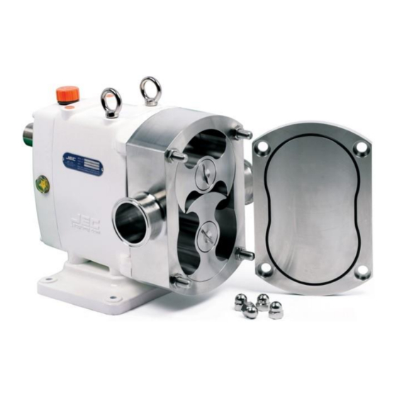
CONSTRUCTION JRZL series Rotary Lobe Pumps can be ordered with bare shaft, i.e. pumps without motor or common bed. Or, ordered as a complete unit with drive motor, coupling & guard, common bed (or trolley) and layout described as below. -
Page 5: Packaging & Transport
PACKAGING & TRANSPORT JRZL series are shipped in non-returnable wooden packaging. Unpack the pump/unit upon delivery and inspect it for visible transport damage. Any damage occurred during the transporting has to be immediately reported to the transport agent after receipt of the consignment. Do not put the damaged products into operation. -
Page 12: Warranty
WARRANTY Terms, Warranty Provisions, Notice of Claims and Limitation of Liability All terms & conditions and prices of sale are based on the applicable JEC price list at the time an order from Customer is received by JEC and are subject to change without notice. No assignment of the purchaser’s rights may be made without consent of JEC. -
Page 13: Safety
SAFETY DO’S & DON’TS DO read and understand these instructions before installing or using the pump. DO use JEC spare parts when replacing a component of the pump. DO NOT service the pump while it is running. DO NOT place the pump in an application where the service ratings are exceeded. DO NOT modify the pump. -
Page 14: Installation
INSTALLATION INSTALLATION 1. Mounting surface should be flat and level. 2. Ensure at least 0.5m clearance around the pump. 3. Normally, pump and drive unit are configured with common bed. If you want other way, feel free to contact JEC. 4. -
Page 15: Check Pump Rotation
CHECK PUMP ROTATION PRINCIPLE OF OPERATION The pumps are of the positive displacement rotary type with lobed rotors. The volume at the inlet increases when the rotors rotate and the product is drawn into the pump. It is then transported in the space between the lobes and the periphery of the pump housing to the discharge side. -
Page 16: Operation
OPERATION TROUBLESHOOTING Problem Cause Solution Pump not turning Interruption of electrical power. Reset circuit breaker, check fuses. Key sheared or missing. Replace. Coupler or belts are not connected. Replace or adjust. Pump shaft or gears sheared. Replace. Wrong rotation. Reverse. Relief valve not properly adjusted. -
Page 17: Cleaning
CLEANING 1. Before cleaning the pump, wear rubber gloves and protective glasses. 2. While CIP and SIP process, do not touch the pump and pipelines. 3. Ensure velocity rate of CIP solutions is adequate to clean entire circuit. For most applications a velocity of 1.52 m/sec is sufficient. -
Page 18: Maintenance
MAINTENANCE ROTOR CASE DISASSEMBLY Prior to removal of pump, the shut-off valves in the suction and discharge pipe work must be closed. If there is any risk that product may be hardened, crystallized or frozen in the pump it should be thoroughly drained and cleaned immediately after use. Similar attention must be applied to the seal flushing system. -
Page 19: Inspection
After pulling out both rotors, rotor case can be separated by sliding along the stud bolt and pulling out from the Gearbox. Inspect the rotor case for wear, clean and continue to seal maintenance, if needed. Fig. 5 In this time, handle and place carefully to keep the right track of position of the top &... -
Page 20: Seal Maintenance
SEAL MAINTENANCE JRZL series is designed by ‘Front Loading Seal’ that the mechanical seal system can be changed or replaced without removing rotor case. Check & inspect all components of seal replacement kit carefully whether there is any damage or defect before installing. - Page 21 Single Mechanical Seal Maintenance Remove the Seal ring from the rotor case & rotor (shown in Figure 13) and inspect them. If any seal is damaged, do not re- use and replace it. Clean both shaft ends and the rotor case before assembling. Push the replacing NEW Seal ring into the rotor case O-ring and turn fit into the seal pins on the seal body after Rotor Case Assembly on page 16.
- Page 22 Place the rotor case face down on the table and pull out carefully the Double seal body out of rotor case by hands shown in Figure 18. Lubricate the replacing double seal body or O-ring and insert it into the rotor case and fit into the Seal pin properly. See ‘Rotor Case Assembly’...
-
Page 23: Rotor Case Assembly
ROTOR CASE ASSEMBLY Before installing the rotor case (31) to the gearbox (1A), make sure to clean the surface of rotor case and Gearbox and check the shim plates surely between rotor case and Gearbox as originally. Assemble the rotor case (31) onto the Gearbox (1A) and secure the four hexa-nuts (46) with reference of below torque set value. -
Page 24: Rotor Clearance
ROTOR CLEARANCE Rotor clearance must be precisely maintained to provide maximum pumping efficiency, yet prevent contact between rotors, rotor case, and front cover during operation. If pumping efficiency is lower than expected or if parts contact has occurred during operation (Within rated differential pressure), check the rotor clearances and adjust, if incorrect. -
Page 25: Rotor Timing
Rotor thickness and body depth are fixed at manufacturer. Therefore, with the correct rotor size selected, the only maintenance adjustment that can be made is the proportion of front and rear clearance. Measure the front clearance as follows: 1. The rotor to rotor housing back face clearance is maintained by the shim(s) (45). 2. - Page 26 6. If the rotor timing is correct, measure the gap of the gear between drive shaft and idle shaft using depth micrometer shown in Figure 28. Adjust the gap using spacer and shim(s) according to the below cases. * If the gap is (+) value (idle shaft is more embossed than drive shaft) as shown in Figure 29, combined 6mm spacer &...
-
Page 27: Gearbox Maintenance
GEARBOX MAINTENANCE Gearbox Disassembly 1. Remove the drain plug and drain the oil. Remove the shaft key (7) on the drive shaft and Gearbox cover bolts (6) from the rear cover (4). Pull the cover off the drive shaft extension. If the cover stuck, use a soft mallet carefully to loosen it. - Page 28 Or pull out the drive & idle shafts by hitting with soft mallet the rear-end of each shaft on the gasket face of the Gearbox. Fig. 35 9. Remove the bearings and spacers (16) together from the shafts by pressing the shaft separated with them. Or remove bearings by puller shown in Figure 36.
- Page 29 Gearbox Assembly 1. Clean and lubricate the front & rear bearing areas of the drive & idle shafts with oil. Fit the front bearing, spacer and rear bearing on the shaft sequentially by arbor press (or heat 120℃(250F) up by heater). Position the gearbox (1) with wet end side facing up and be sure to place carefully for the gasket face(downside) of cover during this time.
- Page 30 4. Place the gear, lock washer (12) and lock nut (12-1) sequentially onto the shafts and hand tighten. In order to ensure proper rotor timing the gears must be installed along with the rotors. Slide the gears on the shafts aligning the slot on the gear with the gear key Fig.
-
Page 31: Lubrication
Lubrication Pump bearings and gear should run in an oil bath. Replacement of these bearings and gear wheels is recommended after 20,000 hours of operation. However, the shorter change intervals required for particularly difficult operating conditions, such High temperature variations High pressure fluctuations Oil in Gearbox is recommended to be changed once a year or every 3,000 operating hours. -
Page 32: Technical Information
TECHNICAL INFORMATION TECHNICAL DATA SPECIFICATIONS Maximum Inlet Pressure ………………………………………………….…… 10 bar (1,000 kPa, 145 psi) Maximum Differential Pressure ……………………………………………… 12 bar (1,200 kPa, 174 psi) Up to 25 bar is available with ‘Front bearing cover’ Maximum Flow Rate ………………………………………………………………… 100 ㎥/hr (440 US GPM) Please consult JEC incase over 100 ㎥/hr up to 450 ㎥/hr Temperature Range ……………………………….……………………... -
Page 33: Dimensional Drawing
DIMENSIONAL DRAWING Dimension (mm) Model No. ZL105-002-20 ZL110-005-20 ZL115-012-12 ZL120-021-08 ZL220-040-12 ZL225-062-08 ZL330-102-12 243.5 128.5 ZL340-144-08 243.5 128.5 ZL440-227-12 ZL450-334-08 Dimension B1 (mm) Weight Volume Model No Ports CLAMP FLANGE ZL105-002-20 1” 0.01 ZL110-005-20 1” 0.01 ZL115-012-12 1 1/2” 0.01 ZL120-021-08 2”... -
Page 34: Parts List
PARTS LIST EXPLODED VIEW / ZL100, ZL200 AND ZL300... - Page 35 All orders for repair parts must be contained the following; 1. Complete model number (located on nameplate). 2. Pump serial number (located on nameplate). 3. Description and part number from the parts list. Below parts list for ZL100 model only. Please ask the ‘Parts list’ to our distributor or us separately for your further reference.
- Page 36 Q'ty ITEM PART NO. Description Material Ass'y Pump PCPI-N3X8-SS Pin, Double Seal SUS304 PMZL-GG1X-PA Gasket Paper PMZL-M08X-PE Plug (M8) MMZL-GBA1-SS Vertical adaptor SUS304 28-1 PCWB-C08X-CS CM W-Bolt M08x20L S45C PCPD-ALL2-SS Pad, Leg feet SS+Rubber MMZL-ET00-SS Rotor bolt, tool, Extraction SUS304 ZL115-GBXH-CW Gearbox Ass'y - White, ZL105/110/115 FCD40...
- Page 37 Q'ty ITEM PART NO. Description Material Ass'y Pump PCOR-A021-NB O-ring, Rotor Bolt(AN021) PCOR-A021-EP O-ring, Rotor Bolt(AN021) EPDM PCOR-A021-FP O-ring, Rotor Bolt(AN021) PMOR-A021-PF O-ring, Rotor Bolt(AN021) Perfluoro PMOR-A021-KA O-ring, Rotor Bolt(AN021) Kalrez PTFE PMOR-A021-PT O-ring, Rotor Bolt(AN021) capsulated Rotor * SUS316L PCPI-N3X8-SS Seal pin, Rotor SUS304...
- Page 38 Q'ty ITEM PART NO. Description Material Ass'y Pump MMZL-105D-SS Rotor Case-1"DIN11851, ZL105 SUS316L Rotor Case-1"DIN2633(FLANGE), MMZL-105F-SS SUS316L ZL105 MMZL-105S-SS Rotor Case-1"DS722.1, ZL105 SUS316L MMZL-105I-SS Rotor Case-1"ISOMALE(IDF), ZL105 SUS316L MMZL-105R-SS Rotor Case-1"RJT, ZL105 SUS316L MMZL-105M-SS Rotor Case-1"SMS, ZL105 SUS316L MMZL-105W-SS Rotor Case-1"Welding neck, ZL105 SUS316L MMZL-105C-SS Rotor Case-1"TRICLAMP, ZL105...
- Page 39 Q'ty ITEM PART NO. Description Material Ass'y Pump MMZL-ML1A-SS Rotor, Multi-Lobe, ZL105 SUS316L MMZL-BW1B-SS Rotor, Bi-Wing, ZL110, ZL110 SUS316L Rotor, Bi-Wing, high temp clearance, MMZL-BW1F-SS SUS316L ZL110 MMZL-ML1B-SS Rotor, Multi-Lobe, ZL110 SUS316L MMZL-SW1A-SS Rotor, Single-Wing, ZL115 SUS316L MMZL-BW1C-SS Rotor, Bi-Wing, ZL115 SUS316L Rotor, Bi-Wing, high temp clearance, MMZL-BW1G-SS...
- Page 40 SINGLE MECHANICAL SEAL & TRIPLE LIP SEAL Triple lip Seal Single Mech. Seal Q'ty ITEM PART NO. Description Material Ass'y Pump PCFW-P06X-SS Flat Washer, M/Seal Gland (Φ6) SUS304 PCWB-M06A-SS Wrench Bolt, M/Seal Gland (M6x10L) SUS304 PCOR-A028-NB O-ring, Rotor (AN028) PCOR-A028-EP O-ring, Rotor (AN028) EPDM PCOR-A028-FP...
- Page 41 DOUBLE MECHANICAL SEAL Q'ty ITEM PART NO. Description Material Ass'y Pump PCOR-A028-NB O-ring, Rotor (AN028) PCOR-A028-EP O-ring, Rotor (AN028) EPDM PCOR-A028-FP O-ring, Rotor (AN028) PMOR-A028-KA O-ring, Rotor (AN028) Kalrez PMOR-A028-PF O-ring, Rotor (AN028) Perfluoro PMZL-SR1X-TC Seal Ring PMZL-SR1X-SI Seal Ring PMZW-SR1B-TC Seal Ring, Rubber Heli-lobe, ZW120 PMZW-SR1B-SI...
- Page 42 O-RING SEAL & DOUBLE O-RING SEAL Q'ty PART NO. Description Material ITEM Ass'y Pump PCFW-P06X-SS Flat Washer, Seal Gland (Φ6) SUS304 PCWB-M06A-SS Wrench Bolt, Gland (M6x10L) SUS304 PCOR-A028-NB O-ring, Rotor (AN028) PCOR-A028-EP O-ring, Rotor (AN028) EPDM PCOR-A028-FP O-ring, Rotor (AN028) PMOR-A028-KA O-ring, Rotor (AN028) Kalrez...
- Page 43 FLUSHED MECHANICAL SEAL Q'ty ITEM PART NO. Description Material Ass'y Pump PCWB-M06A-SS Wrench Bolt, Lip Seal Gland (M6x10L) SUS304 PCOR-A028-NB O-ring, Rotor (AN028) PCOR-A028-EP O-ring, Rotor (AN028) EPDM PCOR-A028-FP O-ring, Rotor (AN028) PMOR-A028-KA O-ring, Rotor (AN028) Kalrez PMOR-A028-PF O-ring, Rotor (AN028) Perfluoro PMZL-SR1X-TC Mech.
- Page 44 All orders for repair parts must be contained the following; 1. Complete model number (located on nameplate). 2. Pump serial number (located on nameplate). 3. Description and part number from the parts list. Below parts list for ZL200 model only. Please ask the ‘Parts list’ to our distributor or us separately for your further reference.
- Page 45 Q'ty ITEM PART NO. Description Material Ass'y Pump PCPD-ALL2-SS Pad, Leg feet SS+Rubber MMZL-ET00-SS Rotor bolt, tool, Extraction SUS304 ZL220-GBXH-CW Gearbox Ass'y - White, ZL220 FCD40 ZL220-GBXH-CS Gearbox Ass'y - Silver, ZL220 FCD40 ZL220-GBXH-SS Gearbox Ass'y - Stainless Steel, ZL220 SUS304 ZL225-GBXH-CW Gearbox Ass'y - White, ZL225...
- Page 46 Q'ty ITEM PART NO. Description Material Ass'y Pump MMZL-220D-SS Rotor Case-2"DIN11851, ZL220 SUS316L Rotor Case-2"DIN2633(FLANGE), MMZL-220F-SS SUS316L ZL220 MMZL-220S-SS Rotor Case-2"DS722.1, ZL220 SUS316L MMZL-220I-SS Rotor Case-2"ISOMALE(IDF), ZL220 SUS316L MMZL-220R-SS Rotor Case-2"RJT, ZL220 SUS316L MMZL-220M-SS Rotor Case-2"SMS, ZL220 SUS316L MMZL-220C-SS Rotor Case-2"TRICLAMP, ZL220 SUS316L MMZL-220K-SS Rotor Case-2"FLANGE, ZL220...
- Page 47 SINGLE MECHANICAL SEAL & TRIPLE LIP SEAL Q'ty ITEM PART NO. Description Material Ass'y Pump PCFW-P06X-SS Flat Washer, M/Seal Gland (Φ6) SUS304 PCWB-M06A-SS Wrench Bolt, M/Seal Gland (M6x10L) SUS304 PCOR-A031-NB O-ring, Rotor (AN031) PCOR-A031-EP O-ring, Rotor (AN031) EPDM PCOR-A031-FP O-ring, Rotor (AN031) PMOR-A031-KA O-ring, Rotor (AN031) Kalrez...
- Page 48 DOUBLE MECHANICAL SEAL Q'ty ITEM PART NO. Description Material Ass'y Pump PCOR-A031-NB O-ring, Rotor (AN031) PCOR-A031-EP O-ring, Rotor (AN031) EPDM PCOR-A031-FP O-ring, Rotor (AN031) PMOR-A031-KA O-ring, Rotor (AN031) Kalrez PMOR-A031-PF O-ring, Rotor (AN031) Perfluoro PMZL-SR2X-TC Seal Ring PMZL-SR2X-SI Seal Ring PCOR-A225-NB O-ring, Rotor Case (AN225) PCOR-A225-EP...
- Page 49 O-RING SEAL & DOUBLE O-RING SEAL Q'ty ITEM PART NO. Description Material Ass'y Pump PCFW-P06X-SS Flat Washer, Seal Gland (Φ6) SUS304 PCWB-M06A-SS Wrench Bolt, Gland (M6x10L) SUS304 PCOR-A031-NB O-ring, Rotor (AN031) PCOR-A031-EP O-ring, Rotor (AN031) EPDM PCOR-A031-FP O-ring, Rotor (AN031) PMOR-A031-KA O-ring, Rotor (AN031) Kalrez...
- Page 50 FLUSHED MECHANICAL SEAL Q'ty ITEM PART NO. Description Material Ass'y Pump Wrench Bolt for Lip Seal Gland PCWB-M06A-SS SUS304 (M6x10L) PCOR-A031-NB O-ring, Rotor (AN031) PCOR-A031-EP O-ring, Rotor (AN031) EPDM PCOR-A031-FP O-ring, Rotor (AN031) PMOR-A031-KA O-ring, Rotor (AN031) Kalrez PMOR-A031-PF O-ring, Rotor (AN031) Perfluoro PMZL-SR2X-TC Mech.
- Page 51 All orders for repair parts must be contained the following; 1. Complete model number (located on nameplate). 2. Pump serial number (located on nameplate). 3. Description and part number from the parts list. Below parts list for ZL300 model only. Please ask the ‘Parts list’ to our distributor or us separately for your further reference.
- Page 52 Q'ty ITEM PART NO. Description Material Ass'y Pump ZL330-GBXH-CW Gearbox Ass'y - White, ZL330 FCD40 ZL330-GBXH-CS Gearbox Ass'y - Silver, ZL330 FCD40 ZL330-GBXH-SS Gearbox Ass'y - Stainless Steel, ZL330 SCS13 ZL340-GBXH-CW Gearbox Ass'y - White, ZL340 FCD40 ZL340-GBXH-CS Gearbox Ass'y - Silver, ZL340 FCD40 ZL340-GBXH-SS Gearbox Ass'y - Stainless Steel, ZL340...
- Page 53 Q'ty ITEM PART NO. Description Material Ass'y Pump MMZL-330D-SS Rotor Case-3"DIN11851, ZL330 SUS316L Rotor Case-3"DIN2633(FLANGE), MMZL-330F-SS SUS316L ZL330 MMZL-330S-SS Rotor Case-3"DS722.1, ZL330 SUS316L MMZL-330I-SS Rotor Case-3"ISOMALE(IDF), ZL330 SUS316L MMZL-330R-SS Rotor Case-3"RJT, ZL330 SUS316L MMZL-330M-SS Rotor Case-3"SMS, ZL330 SUS316L MMZL-330C-SS Rotor Case-3"TRICLAMP, ZL330 SUS316L MMZL-330K-SS Rotor Case-3"...
- Page 54 SINGLE MECHANICAL SEAL & TRIPLE LIP SEAL Q'ty PART NO. Description Material ITEM Ass'y Pump PCFW-P06X-SS Flat Washer, M/Seal Gland (Φ6) SUS304 PCWB-M06A-SS Wrench Bolt, M/Seal Gland (M6x10L) SUS304 PCOR-A142-NB O-ring, Rotor (AN142) PCOR-A142-EP O-ring, Rotor (AN142) EPDM PCOR-A142-FP O-ring, Rotor (AN142) PMOR-A142-KA O-ring, Rotor (AN142) Kalrez...
- Page 55 DOUBLE MECHANICAL SEAL Q'ty ITEM PART NO. Description Material Ass'y Pump PCOR-A142-NB O-ring, Rotor (AN142) PCOR-A142-EP O-ring, Rotor (AN142) EPDM PCOR-A142-FP O-ring, Rotor (AN142) PMOR-A142-KA O-ring, Rotor (AN142) Kalrez PMOR-A142-PF O-ring, Rotor (AN142) Perfluoro PMZL-SR3X-TC Seal Ring PMZL-SR3X-SI Seal Ring PMZW-SR3B-TC Seal Ring, Rubber Heli-lobe, ZW340 PMZW-SR3B-SI...
- Page 56 O-RING SEAL & DOUBLE O-RING SEAL Q'ty ITEM PART NO. Description Material Ass'y Pump PCFW-P06X-SS Flat Washer, Seal Gland (Φ6) SUS304 PCWB-M06A-SS Wrench Bolt, Gland (M6x10L) SUS304 PCOR-A142-NB O-ring, Rotor (AN142) PCOR-A142-EP O-ring, Rotor (AN142) EPDM PCOR-A142-FP O-ring, Rotor (AN142) PMOR-A142-KA O-ring, Rotor (AN142) Kalrez...
- Page 57 FLUSHED MECHANICAL SEAL Q'ty ITEM PART NO. Description Material Ass'y Pump PCWB-M06A-SS Wrench Bolt, Lip Seal Gland (M6x10L) SUS304 PCOR-A142-NB O-ring, Rotor (AN142) PCOR-A142-EP O-ring, Rotor (AN142) EPDM PCOR-A142-FP O-ring, Rotor (AN142) PMOR-A142-KA O-ring, Rotor (AN142) Kalrez PMOR-A142-PF O-ring, Rotor (AN142) Perfluoro PMZL-SR3X-TC Mech.
- Page 58 EXPLODED VIEW / ZL400...
- Page 59 All orders for repair parts must be contained the following; 1. Complete model number (located on nameplate). 2. Pump serial number (located on nameplate). 3. Description and part number from the parts list. Below parts list for ZL400 model only. Please ask the ‘Parts list’ to our distributor or us separately for your further reference.
- Page 60 Q'ty ITEM PART NO. Description Material Ass'y Pump ZL440-GBXH-CW Gearbox Ass'y - White, ZL440 FCD40 ZL440-GBXH-CS Gearbox Ass'y - Silver, ZL440 FCD40 ZL450-GBXH-CW Gearbox Ass'y - White, ZL450 FCD40 ZL450-GBXH-CS Gearbox Ass'y - Silver, ZL450 FCD40 Rotor Case * SUS316L MMZL-FC4A-SS Front Cover SUS316L...
- Page 61 Q'ty ITEM PART NO. Description Material Ass'y Pump MMZL-440D-SS Rotor Case-4"DIN11851, ZL440 SUS316L Rotor Case-4"DIN2633(FLANGE), MMZL-440F-SS SUS316L ZL440 MMZL-440S-SS Rotor Case-4"DS722.1, ZL440 SUS316L MMZL-440I-SS Rotor Case-4"ISO MALE(IDF), ZL440 SUS316L MMZL-440R-SS Rotor Case-4"RJT, ZL440 SUS316L MMZL-440M-SS Rotor Case-4"SMS, ZL440 SUS316L MMZL-440C-SS Rotor Case-4"TRI-CLAMP, ZL440 SUS316L MMZL-450D-SS...
- Page 62 SINGLE MECHANICAL SEAL & TRIPLE LIP SEAL Single Mech. Seal Triple Lip Seal Q'ty ITEM PART NO. Description Material Ass'y Pump PCFW-P06X-SS Flat Washer, M/Seal Gland (Φ6) SUS304 PCWB-M06A-SS Wrench Bolt, M/Seal Gland (M6x10L) SUS304 PCOR-A151-NB O-ring, Rotor (AN151) PCOR-A151-EP O-ring, Rotor (AN151) EPDM PCOR-A151-FP...
- Page 63 DOUBLE MECHANICAL SEAL Q'ty ITEM PART NO. Description Material Ass'y Pump PCOR-A151-NB O-ring, Rotor (AN151) PCOR-A151-EP O-ring, Rotor (AN151) EPDM PCOR-A151-FP O-ring, Rotor (AN151) PMOR-A151-KA O-ring, Rotor (AN151) Kalrez PMOR-A151-PF O-ring, Rotor (AN151) Perfluoro PMZL-SR4X-TC Seal Ring PMZL-SR4X-SI Seal Ring PCOR-A235-NB O-ring, Rotor Case (AN235) PCOR-A235-EP...
- Page 64 O-RING SEAL & DOUBLE O-RING SEAL Double O-ring Seal O-ring Seal Q'ty ITEM PART NO. Description Material Ass'y Pump PCFW-P06X-SS Flat Washer, Seal Gland (Φ6) SUS304 PCWB-M06A-SS Wrench Bolt, Gland (M6x10L) SUS304 PCOR-A151-NB O-ring, Rotor (AN151) PCOR-A151-EP O-ring, Rotor (AN151) EPDM PCOR-A151-FP O-ring, Rotor (AN151)
- Page 65 FLUSHED MECHANICAL SEAL Q'ty ITEM PART NO. Description Material Ass'y Pump PCWB-M06A-SS Wrench Bolt , Lip Seal Gland (M6x10L) SUS304 PCOR-A151-NB O-ring , Rotor (AN151) PCOR-A151-EP O-ring , Rotor (AN151) EPDM PCOR-A151-FP O-ring , Rotor (AN151) PMOR-A151-KA O-ring, Rotor (AN151) Kalrez PMOR-A151-PF O-ring , Rotor (AN151)
- Page 66 JEC LTD. All technical information and its contents contained in this manual is subject to change without prior notice and does not represent a commitment on the part of JEC Ltd. Any part of this 15-26, Beodeul-ro, Paltan-myun, Hwaseong-si, Gyeonggi- manual may NOT be reproduced, copied, duplicated or transmitted in any form or by any means, electronic or do, 18578, Rep.
Need help?
Do you have a question about the JRZL Series and is the answer not in the manual?
Questions and answers