Advertisement
Quick Links
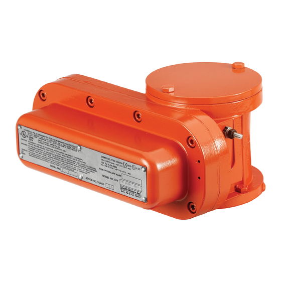
Universal Pulse Transmitter (UPT)
Installation/Service
Bulletin MN01045 Issue/Rev. 0.7 (11/17)
General
The Smith Meter
Model UPT (Universal Pulse) Transmit-
®
ter is a photo-electric, dual channel, high resolution, pulse
generator that is directly connected to the output shaft of a
positive displacement meter.
The UPT Transmitter is installed at the lowest level in the
meter accessory stack. It is designed to be mounted directly
on the meter dome adaptor and replaces the manual cali-
brator. If other mechanical stack accessories are required,
a calibrator adaptor kit is used for mounting the manual
calibrator above the UPT Transmitter.
Reference Publications
Specification Bulletin
SS01105
Parts List
PO01056
(P0907.05)
Receipt of Equipment
When the equipment is received, the outside packing case
should be checked immediately for any shipping damage.
If the packing case has been damaged, the local carrier
should be notified at once regarding his liability. Carefully
remove the unit from its packing case and inspect for
damaged or missing parts.
If damage has occurred during shipment or parts are
missing, a written report should be submitted to the Inside
Sales Department, Measurement Solutions, PO Box 10428,
Erie, Pennsylvania 16514.
Prior to installation, the unit should be stored in its original
packing case and protected from adverse weather condi-
tions and abuse.
Mechanical Installation
When ordered with a Smith Meter
(PD) meter, the Model UPT Transmitter will normally be
factory installed directly on the meter. The following steps
are required for field mounting the UPT Transmitter to a
Smith Meter PD meter:
positive displacement
®
1. Remove all accessories (counters, mechanical temperature
compensators, transmitters, etc.) from the meter.
2. Remove the existing calibrator, located inside the meter
dome adaptor.
a. Remove the cap protecting the external calibrator
adjusting stem by removing the two mounting screws.
b. Indicate the calibrator setting with a line that intersects the
calibrator dial and its adjacent part.
c. Remove the calibrator adjusting assembly by removing
the two mounting screws and carefully withdraw the stem
assembly from the housing without changing the adjusting
screw.
d. Remove the calibrator from the meter dome adaptor by
removing the two small hold-down screws and carefully
rotating the calibrator body clockwise.
e. Attach the blind plate (provided in the adaptation
kit) over the calibrator stem assembly hole.
MANUAL
Advertisement

Summary of Contents for Smith Meter UPT
- Page 1 The UPT Transmitter is installed at the lowest level in the meter accessory stack. It is designed to be mounted directly on the meter dome adaptor and replaces the manual cali- brator.
- Page 2 P/N 529288011. If a live calibrator is required on damage. top of the UPT Transmitter then a remote calibrator kit is For wiring systems utilizing conduit, an Ex certified sealing required P/N 529288001.
-
Page 3: Wiring Diagram
Wiring Diagram Standard Version Pin Rotation of Transmitter Shaft Reference Function Color Connections Dimensions Drawing Below Electronics Ground white [ 1 ] Input Power (12-24 Vdc) brown [ 2 ] Counter-Clockwise Clockwise Channel "B" Output grey [ 3 ] Leading Lagging Channel "B"... -
Page 4: Maintenance
Maintenance The UPT Transmitter has all self-lubricating bearings and a sealed transmitter assembly so preventative maintenance is not required. Mechanical Maintenance to Transmitter Step 1. Remove the eight cover screws and tap the Step 3. Remove the coupling and pull the shaft out. - Page 5 Step 7. Step 5. a. Remove encoder from housing. Inspect terminal block and encoder for damage, corrosion or wear and replace if b. Remove longer inside screws followed needed. by shorter inside screws to expose the o-ring. Inspect o-ring, replace if damaged or cracked.
- Page 6 Step 11. a. Insert shaft down through the top and Step 9. a. Tighten T-Bar with the encoder attached through the encoder. onto housing. Note: You may need to tap the shaft until it slides through completely. b. Tighten terminal block mounting bracket screws.
- Page 7 Step 12. Attach the coupling on the end of the shaft Step 14. Close the cover and tighten the eight cap and insert hairspring cotter pin. screws around the perimeter of the cover using the sequence shown. The final torque should be 15 LB-FT / 180 LB-IN (20.3 Nm / Step 12 207.4 Kg.
-
Page 8: Storage Instruction
• Use conduit seal-off fitting as per applicable electrical code • Do Not leave units installed with open seal-off fitting and / or removed covers where moisture can enter into the UPT housing Revisions included in MN01045 Issue/Rev. 0.7 (11/17): Step 13 revised;...
Need help?
Do you have a question about the UPT and is the answer not in the manual?
Questions and answers