Table of Contents
Advertisement
Quick Links
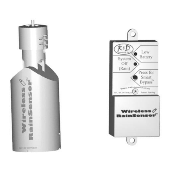
The Wireless RainSensor
For Irrigation Systems
Transmitter
I
:
NTRODUCTION
Congratulations on your purchase of the Wireless Rain Sensor. No spe-
cial tools are required to install the Wireless Rain Sensor, so you'll be up
and running in minutes.
Please read through these instructions in their entirety before attempting
to install the Wireless RainSensor. If you are unsure about the proper
wiring, please have a qualified contractor perform the installation for
you. Installation should also be performed with adherence to local codes.
Additional information is available at www.rainsensor.com.
PLEASE NOTE:
NOT
The Receiver should
be directly connected to 120/240VAC.
SHOULD
The Receiver
be mounted indoors or in a protective enclosure.
NOT
The Transmitter should
be submerged in water.
Usted habla español?
Este manual de instrucción está también disponible en español. Por
favor contacte su distribuidor, or llame al 1-888-301-3818.
R&D Engineering, Inc., Manasquan, NJ
TM
Receiver
Advertisement
Table of Contents

Summary of Contents for R&D Wireless Rain Sensor
- Page 1 NTRODUCTION Congratulations on your purchase of the Wireless Rain Sensor. No spe- cial tools are required to install the Wireless Rain Sensor, so you’ll be up and running in minutes. Please read through these instructions in their entirety before attempting to install the Wireless RainSensor.
- Page 2 UICK TART NSTRUCTIONS For the experienced installer, the following instructions can be used. 1. Mount Receiver adjacent to controller with screws provided. 2. Turn off or disconnect power to the timer/controller. 3. Attach Receiver control wires to the sensor inputs OR a.
- Page 3 A. Controllers with NO Sensor Inputs, NO Pump Start or Master Valve: (Fig. 3) Disconnect the common con- Fig. 3 Valve Controller / Timer Valve Controller / Timer trol wire from the common Valve Valve terminal of the controller. Terminals Terminals 1 2 3 4 1 2 3 4...
- Page 4 The Receiver requires a nominal voltage of 24V to power the unit. ∗∗Turn off / Disconnect Power to the Controller/timer before proceeding! A. Controllers WITH 24V Terminals: (Fig. 3) 24V terminals are present on the majority of controllers. Simply attach the Red and Black Receiver wires to these two terminals (order does not matter).
- Page 5 : (Fig. 8) DJUSTMENT Fig. 8 The Wireless RainSensor can be adjusted to detect rainfall quantities of 1/8", 1/4", 1/2", 3/4" or 1". Rotate the cap on the Transmitter body so the pins are located in the desired rain- fall amount slot. Be sure to align the slots and pins properly as this adjustment should not re- quire excessive force .
- Page 6 PERATION Normal Operation: When the Wireless RainSensor activates due to sufficient rainfall, the “System Off - Rain” light will remain illuminated on the Receiver. After the rain sensor “dries out”, the controller will resume its normal watering schedule. Smart Bypass Your Wireless RainSensor can be temporarily deactivated by using the built in Smart Bypass button.
- Page 7 ROUBLESHOOTING UPPORT Please visit our website at www.rainsensor.com for troubleshooting help. You may also contact R&D Engineering directly through our help-line at 888-301-3818. PTIONAL QUIPMENT CCESORIES The following are optional components that may be purchased from your local supplier or from R&D Engineering directly. Combination Rain/Freeze sensor model (part # WRS1-F) 120 - 24VAC Transformer (part # TRN120) 240 - 24VAC Transformer (part # TRN240)
- Page 8 PECIFICATIONS Mounting: “Quick-Clip” Gutter Bracket, Screws or Pole mount. Rain Sensor Transmitting Range: up to 300 feet LOS Sensor: Industry Standard Hygroscopic discs with adjustable rain sensitivity Optional Freeze Sensor available now! Transmitter Average Battery Life: 5 years Battery Type: (2) CR2032 - 3V cells Operating Temperature: -20 F to 120 Receiver Power: 22-28 VAC/VDC, 100mA (from existing timer...
Need help?
Do you have a question about the Wireless Rain Sensor and is the answer not in the manual?
Questions and answers