Table of Contents
Advertisement
EASY-ROTOR-CONTROL M V2.2
Instructions
Congratulations for buying your EASY-ROTOR-CONTROL M (shortly ERC-M). This
document will guide you through the needed steps for assembly and configuration of
the ERC-M. You will reach the best result by following these instructions step by step.
Table of contents
Safety-Instructions ................................................................................................................. 2
1. ERC-M USB ...................................................................................................................... 3
1.1 Bill of material (BOM)................................................................................................. 3
1.2 Preparation of USB-modul........................................................................................... 4
1.3 Assembly of the ERC-M USB PCB............................................................................. 4
1.4 Connection of the DC-supply and check of the voltage-regulator............................... 8
1.5 Insert ICs and the USB-module ................................................................................... 9
1.6 Establishing the USB-connection................................................................................. 9
2. ERC-M RS232 ................................................................................................................. 10
2.1 Bill of material (BOM)............................................................................................... 10
2.2 Assembly of RS232 cable .......................................................................................... 11
2.3 Assembly of the ERC-M RS232 PCB........................................................................ 12
2.4 Connection of the DC-supply and check of the voltage-regulator............................. 16
2.5 Insert ICs .................................................................................................................... 17
3. LAN-Interface (optional) ................................................................................................. 18
3.1 Bill of material ........................................................................................................... 18
3.2 Assembly of the LAN-Interface ................................................................................. 18
3.4 Check of the DC/DC-converter.................................................................................. 20
3.5 Device-Installer .......................................................................................................... 21
3.6 Installation of the COM-Port-Redirector (CPR) ........................................................ 21
4. Rotor-Card (optional) ....................................................................................................... 23
4.1 Bill of material ........................................................................................................... 23
4.2 Assembly of the Rotor-Card PCB .............................................................................. 23
4.3 Connection of the Rotor-Card .................................................................................... 25
4.4 Test of Rotor-Card ..................................................................................................... 26
4.5 Installation of the Rotor-Card into a control-box....................................................... 26
5. SlimLine housing (optional)............................................................................................. 28
6. HID AZ/AZ or AZ/EL and desktop housing (optional)................................................... 29
6.1 Bill of material ........................................................................................................... 29
6.2 Assembly of bottom-side HID-PCB .......................................................................... 30
6.3 Assembly of top-side HID-PCB AZ/AZ (dual azimuth) ........................................... 31
6.5 Cable to connect the HID to ERC-M ......................................................................... 35
6.6 Cable to connect the ERC-M to rear-side D-SUB ..................................................... 35
6.7 Mechanical integration into the desktop-housing ...................................................... 36
7. The Service-Tool.............................................................................................................. 38
7.1 Configuration of the COM-Port ................................................................................. 38
___________________________________________________________________________
© Ing.-Büro E. Alba de Schmidt
Tannenstr. 16
86836 Untermeitingen / Germany
This document is for the user only. Any publishing (printed or in electronic form) is not allowed.
Page 1 of 44
Instructions
web :
www.schmidt-alba.de
email :
erc@schmidt-alba.de
Advertisement
Table of Contents

Subscribe to Our Youtube Channel
Related Manuals for erc EASY-ROTOR-CONTROL M


Summary of Contents for erc EASY-ROTOR-CONTROL M
-
Page 1: Table Of Contents
Congratulations for buying your EASY-ROTOR-CONTROL M (shortly ERC-M). This document will guide you through the needed steps for assembly and configuration of the ERC-M. You will reach the best result by following these instructions step by step. Table of contents Safety-Instructions ......................... -
Page 2: Safety-Instructions
Appendix1: Pin-out of D-SUB15 ERC-M ............... 41 Appendix2: Pin-out of mini-DIN rotor-card ..............41 Appendix3: Connection of rotor-card to ERC-M ............41 Appendix4: Pin-out of the HID-connector on ERC-M ............ 42 Appendix5: Schematics Rotor-Card................. 42 Appendix6: Schematics ERC-M ..................43 Appendix7: Schematics HID.................... -
Page 3: Erc-M Usb
1. ERC-M USB If your kit is RS232 (not USB) go to chapter 2. 1.1 Bill of material (BOM) The BOM is in the order how you should use the parts. ERC-M USB V2.2 Bill Of Material QTY Type Value Reference... -
Page 4: Preparation Of Usb-Modul
Solder the 8-pin pin-header 90° to the bottom side of the USB-module. Take care, that the shorter side of the pins is soldered to the USB-Module. 1.3 Assembly of the ERC-M USB PCB Assemble and solder the components according to the following drawings. - Page 5 EASY-ROTOR-CONTROL M V2.2 Instructions Not to be assembled components are marked grey in the assembly drawing. ___________________________________________________________________________ © Ing.-Büro E. Alba de Schmidt web : www.schmidt-alba.de Tannenstr. 16 Page 5 of 44 email : erc@schmidt-alba.de 86836 Untermeitingen / Germany This document is for the user only. Any publishing (printed or in electronic form) is not allowed.
- Page 6 EASY-ROTOR-CONTROL M V2.2 Instructions USB-Module ___________________________________________________________________________ © Ing.-Büro E. Alba de Schmidt web : www.schmidt-alba.de Tannenstr. 16 Page 6 of 44 email : erc@schmidt-alba.de 86836 Untermeitingen / Germany This document is for the user only. Any publishing (printed or in electronic form) is not allowed.
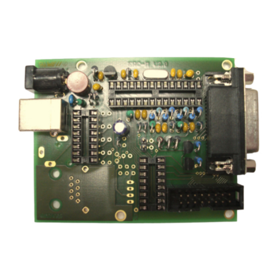
- Page 7 EASY-ROTOR-CONTROL M V2.2 Instructions Check carefully the assembly. So, this is how it should look like. ___________________________________________________________________________ © Ing.-Büro E. Alba de Schmidt web : www.schmidt-alba.de Tannenstr. 16 Page 7 of 44 email : erc@schmidt-alba.de 86836 Untermeitingen / Germany This document is for the user only. Any publishing (printed or in electronic form) is not allowed.
-
Page 8: Connection Of The Dc-Supply And Check Of The Voltage-Regulator
First a little electrical test should be performed: 1.4 Connection of the DC-supply and check of the voltage-regulator Now put the jumper on the 1x2 pinheader JP1 (the jumper supplies the ERC with +5V). After checking all assembled components for identity, polarization and solder-bridges, prepare a DC- cable with 10 to 15VDC by using the DC-connector supplied with the kit or use any other DC-supply with that voltage and an appropriate DC-Connector of 2.1/5.5mm. -
Page 9: Insert Ics And The Usb-Module
Also insert the USB-module on the socket of IC3 as shown. 1.6 Establishing the USB-connection Plug the USB-B-connector to the ERC-M and the USB-A-connector to a free USB-connector on your Depending on your operating-system, you will be asked to install an USB-driver. This driver is available on the CD delivered with your kit. -
Page 10: Erc-M Rs232
2. ERC-M RS232 If your kit is USB (not RS232) go to chapter 1. 2.1 Bill of material (BOM) The BOM is in the order how you should use the parts. ERC-M RS232 V2.2 Bill Of Material QTY Type Value Reference... -
Page 11: Assembly Of Rs232 Cable
TXD: tip-contact of the phone-jack : to PIN 3 of the DSUB NOTE: If you use the ERC-M in MASTER-SLAVE-mode over RS232, the pins for RXD and TXD must be crossed for the Master-ERC-M: TXD to Pin 2 and RXD to Pin3 of the D-SUB. ___________________________________________________________________________ ©... -
Page 12: Assembly Of The Erc-M Rs232 Pcb
EASY-ROTOR-CONTROL M V2.2 Instructions 2.3 Assembly of the ERC-M RS232 PCB Assemble and solder the components according to the following drawings. Please read the following instructions before you start: 1. The vertical assembled Diodes should have a distance (1-2mm) to the PCB while soldering. - Page 13 EASY-ROTOR-CONTROL M V2.2 Instructions ___________________________________________________________________________ © Ing.-Büro E. Alba de Schmidt web : www.schmidt-alba.de Tannenstr. 16 Page 13 of 44 email : erc@schmidt-alba.de 86836 Untermeitingen / Germany This document is for the user only. Any publishing (printed or in electronic form) is not allowed.
- Page 14 EASY-ROTOR-CONTROL M V2.2 Instructions ___________________________________________________________________________ © Ing.-Büro E. Alba de Schmidt web : www.schmidt-alba.de Tannenstr. 16 Page 14 of 44 email : erc@schmidt-alba.de 86836 Untermeitingen / Germany This document is for the user only. Any publishing (printed or in electronic form) is not allowed.
- Page 15 EASY-ROTOR-CONTROL M V2.2 Instructions Check carefully the assembly. So, this is how it should look like. ___________________________________________________________________________ © Ing.-Büro E. Alba de Schmidt web : www.schmidt-alba.de Tannenstr. 16 Page 15 of 44 email : erc@schmidt-alba.de 86836 Untermeitingen / Germany This document is for the user only. Any publishing (printed or in electronic form) is not allowed.
-
Page 16: Connection Of The Dc-Supply And Check Of The Voltage-Regulator
2.4 Connection of the DC-supply and check of the voltage-regulator Now put the jumper on the 1x2 pinheader JP1 (the jumper supplies the ERC with +5V). After checking all assembled components for identity, polarization and solder-bridges, prepare a DC- cable with 10 to 15VDC by using the DC-connector supplied with the kit or use any other DC-supply with that voltage and an appropriate DC-Connector of 2.1/5.5mm. -
Page 17: Insert Ics
EASY-ROTOR-CONTROL M V2.2 Instructions 2.5 Insert ICs The pins of the ICs have to bend before you can put them into their sockets. Use a hard base (e.g. your working desk) and bend the row of pins slightly, that they get an angle of 90° . -
Page 18: Lan-Interface (Optional)
EASY-ROTOR-CONTROL M V2.2 Instructions 3. LAN-Interface (optional) 3.1 Bill of material The BOM is in the order how you should use the parts. ERC-M V2.0 LAN Bill Of Material QTY Type Value Reference Comments 1 Diode 1N4004 alt. 1N4007 2 Capacitor ceramic... - Page 19 EASY-ROTOR-CONTROL M V2.2 Instructions ___________________________________________________________________________ © Ing.-Büro E. Alba de Schmidt web : www.schmidt-alba.de Tannenstr. 16 Page 19 of 44 email : erc@schmidt-alba.de 86836 Untermeitingen / Germany This document is for the user only. Any publishing (printed or in electronic form) is not allowed.
-
Page 20: Check Of The Dc/Dc-Converter
EASY-ROTOR-CONTROL M V2.2 Instructions This is how it should look like: 3.4 Check of the DC/DC-converter After checking all assembled components for identity, polarization and solder-bridges, connect 10 to 15VDC to connector J1 as already performed in chapter 1.3. After connecting DC correctly, you should measure +3.3VDC +/-0.4V at the testpoint shown against GND. -
Page 21: Device-Installer
3.5 Device-Installer The Device-Installer is needed to assign an IP-address to the LAN-Unit: The Device-Installer is available on the disk supplied with your ERC-M in the LANTRONIX-folder. You may find a newer version on the LANTRONIX homepage at www.lantronix.com. First connect the ERC-M with the cross-over patch-cable to your PC. - Page 22 EASY-ROTOR-CONTROL M V2.2 Instructions Start the setup with the file: setup_cpr_x86x64cd_4.3.0.0.exe You will find a quick-start-guide for CPR in the LANTRONIX-folder on the CD: Com-Port-Redirector_QS.PDF By default, the serial speed of the LAN-device is set to 9600 Baud. If you want to use it with a different speed, as your application doesn’t support 9600 Baud, change the speed settings with the Web-...
-
Page 23: Rotor-Card (Optional)
EASY-ROTOR-CONTROL M V2.2 Instructions 4. Rotor-Card (optional) 4.1 Bill of material The BOM is in the order how you should use the parts. Rotor-card V1.6 Bill Of Material QTY Type Value Reference Comments 1 PCB RC 2-layer 67.5x43.6mm V1.6 1 Capacitor ceramic... - Page 24 EASY-ROTOR-CONTROL M V2.2 Instructions After assembly, attach the 2 mounting-angles with 2 screws and 2 nuts. Use spring-washers below the nuts. ___________________________________________________________________________ © Ing.-Büro E. Alba de Schmidt web : www.schmidt-alba.de Tannenstr. 16 Page 24 of 44 email : erc@schmidt-alba.de 86836 Untermeitingen / Germany This document is for the user only.
-
Page 25: Connection Of The Rotor-Card
Check carefully the assembly. So, this is how it should look like. 4.3 Connection of the Rotor-Card The connection between Rotor-Card and ERC-M has to be done with the 6-pin Mini-DIN-cable supplied with the Rotor-Card-kit. The connections are shown in the next picture. Connect the pins with the same colour between the Mini-DIN-connector and the D-SUB-connector for axis 1 or axis 2. -
Page 26: Test Of Rotor-Card
The Rotor-Card should be electrically tested before you connect it to the rotator-control-box. Perform the test as follows: Connect the Rotor-Card to the ERC-M by use of the cable prepared in chapter 4.3 Connect 12V DC to the DC-connector of the ERC-M. The Rotor-Cards cannot work without the external DC-supply. - Page 27 Mount the rotor-card to the control-box using the 2 screws and spring-washers below the screws. The wiring of the rotor-card to the different control-boxes is shown in the Installation-Guide provided on the CD of your ERC-M-kit. ___________________________________________________________________________ © Ing.-Büro E. Alba de Schmidt web : www.schmidt-alba.de...
-
Page 28: Slimline Housing (Optional)
Put the 4 rubber-feet to the bottom-side of the housing Remove the 2 distance-bolts from the DSUB- Mount the back-panel to the ERC-M using the 2 connector on the ERC-M bolts Slide the ERC-M into the housing and mount the Pull the label from its foil and put it carefully on back-panel to the housing. -
Page 29: Hid Az/Az Or Az/El And Desktop Housing (Optional)
6. HID AZ/AZ or AZ/EL and desktop housing (optional) The HID is a human-interface-device and provides a 2x16 character LCD-display, 6 LEDs and 4 pushbuttons to the user. The HID and ERC-M is mounted in a powder-coated and silkscreen printed black sheet-metal-housing. -
Page 30: Assembly Of Bottom-Side Hid-Pcb
EASY-ROTOR-CONTROL M V2.2 Instructions 6.2 Assembly of bottom-side HID-PCB Assemble and solder the components according to the following drawings. Please read the following instructions before you start: Take care of polarization of the following components: Diodes D1,D2,D3,D4 Box-header X2 Those components are marked red in the following drawing. -
Page 31: Assembly Of Top-Side Hid-Pcb Az/Az (Dual Azimuth)
EASY-ROTOR-CONTROL M V2.2 Instructions 6.3 Assembly of top-side HID-PCB AZ/AZ (dual azimuth) If your housing is AZ/EL (azimuth and elevation) proceed with step 6.4 First assemble the LCD with the 5mm spacers, screws, nuts and spring-washers to the PCB. Put the 16-pole pin-header between PCB and LCD before mounting. - Page 32 EASY-ROTOR-CONTROL M V2.2 Instructions Hint: Only solder 1 leg of the switches and LEDs, check for alignment and than solder the remaining pins. Use the 3x12x4mm spacers for the LEDs to fix them in the right distance from the PCB.
-
Page 33: Assembly Of Top-Side Hid-Pcb Az/El (Azimuth&Elevation)
EASY-ROTOR-CONTROL M V2.2 Instructions 6.4 Assembly of top-side HID-PCB AZ/EL (azimuth&elevation) If your housing is AZ/AZ (dual azimuth) go back to step 6.3 First assemble the LCD with the 5mm spacers, screws, nuts and spring-washers to the PCB. Put the 16-pole pin-header between PCB and LCD before mounting. - Page 34 EASY-ROTOR-CONTROL M V2.2 Instructions Use the 3x12x4mm spacers for the LEDs to fix them in the right distance from the PCB. Put the 19mm domes on top of the switches. This is how it should look like: ___________________________________________________________________________ © Ing.-Büro E. Alba de Schmidt web : www.schmidt-alba.de...
-
Page 35: Cable To Connect The Hid To Erc-M
Bend the flat-ribbon-cable on both ends over the top of the connector and put the strain-relief on. 6.6 Cable to connect the ERC-M to rear-side D-SUB Take the remaining 200mm of the flat-ribbon-cable and remove 1 wire from the 16-pole cable to get a 15-pole cable (don’t remove the red wire, take the opposite site) -
Page 36: Mechanical Integration Into The Desktop-Housing
4 screws 2.9x6.5mm. the HID into the desktop-housing with 4 Allen-screws using the Allen-tool provided with the kit. Mount the ERC-M-PCB to the housing with Allen- Fold the 15-pole flat-ribbon-cable as shown and put screws. the DSUB-connectors as shown and mount the... - Page 37 EASY-ROTOR-CONTROL M V2.2 Instructions Attach the 16-pole flat-ribbon-cable into the Connect the ERC-M to DC-supply or USB to check connectors as shown. contrast settings. After start-up you should see a start-up-screen like this: Adjust the contrast with the potentiometer R1 on the backside of the HID-PCB.
-
Page 38: The Service-Tool
COM-Port. Choose the right COM-Port. The Service Tool will check the availability of the ERC-M at the chosen COM-Port. If successful, the Service Tool will read the configuration-parameters of the ERC-M and populates the configuration- and the calibration-windows. -
Page 39: Theory Of Operation
(or GS-232A) or DCU-1 protocol from the programs that support controlling rotators. The ERC-M takes the task to move the rotator to the desired position or to stop the rotator while it is moving. Also changes of the direction are possible while the rotator is moving. The current position of the rotators is calculated from the measured rotor-feedback-voltages AZ and EL. -
Page 40: Connect The Erc-M To Other Programs
AZ only 11. Connect the ERC-M to other programs Please take care about the following issues, if you want to control your ERC-M with other programs : Choose the right COM-port COM-port-speed in the program must be same as in ERC-M... -
Page 41: Appendix
Instructions Appendix Appendix1: Pin-out of D-SUB15 ERC-M Connector seen from outside to the female connector on ERC-M or on the back of the desktop- housing. Appendix2: Pin-out of mini-DIN rotor-card Connector seen from outside to the female connector on the rotor-card. -
Page 42: Appendix4: Pin-Out Of The Hid-Connector On Erc-M
EASY-ROTOR-CONTROL M V2.2 Instructions Appendix4: Pin-out of the HID-connector on ERC-M 8 10 12 14 16 9 11 13 15 LCD E LCD RS Keyboard Common LED AUX2 LED AUX1 LCD D7, Keyboard UP LED DWN LCD D6, Keyboard DWN... -
Page 43: Appendix6: Schematics Erc-M
EASY-ROTOR-CONTROL M V2.2 Instructions Appendix6: Schematics ERC-M ___________________________________________________________________________ © Ing.-Büro E. Alba de Schmidt web : www.schmidt-alba.de Tannenstr. 16 Page 43 of 44 email : erc@schmidt-alba.de 86836 Untermeitingen / Germany This document is for the user only. Any publishing (printed or in electronic form) is not allowed. -
Page 44: Appendix7: Schematics Hid
EASY-ROTOR-CONTROL M V2.2 Instructions Appendix7: Schematics HID ___________________________________________________________________________ © Ing.-Büro E. Alba de Schmidt web : www.schmidt-alba.de Tannenstr. 16 Page 44 of 44 email : erc@schmidt-alba.de 86836 Untermeitingen / Germany This document is for the user only. Any publishing (printed or in electronic form) is not allowed.
Need help?
Do you have a question about the EASY-ROTOR-CONTROL M and is the answer not in the manual?
Questions and answers