
Subscribe to Our Youtube Channel
Summary of Contents for PMV P5
- Page 1 Manual P5/EP5 Valve Control System alve Control System – 1 – Manual P5/EP5 23740/98.10...
- Page 2 également que leur mise en service est interdite tant qu'il n'a pas été constaté que cette machine/application satisfait également à la directive CE 89/392 CEE et CE/89/336/CEE. Cette déclaration de fournisseur est valable pour les types d'appareils PMV suivants: P5, EP5, F5. Mr. Jan-Eric Andersson President, Palmstiernas Instrument AB –...
-
Page 3: Table Of Contents
I/P Unit, EP5 How to mount the I/P Unit Maintenance 15-19 Pilot valve Diaphragm Feedback spring Balance arm Lower arm O-rings Filter plug Feedback Unit Trouble shooting Technical Data Exploded Drawing Spare part list Approvals 24-27 – 3 – Manual P5/EP5 23740/98.10... -
Page 4: Introduction
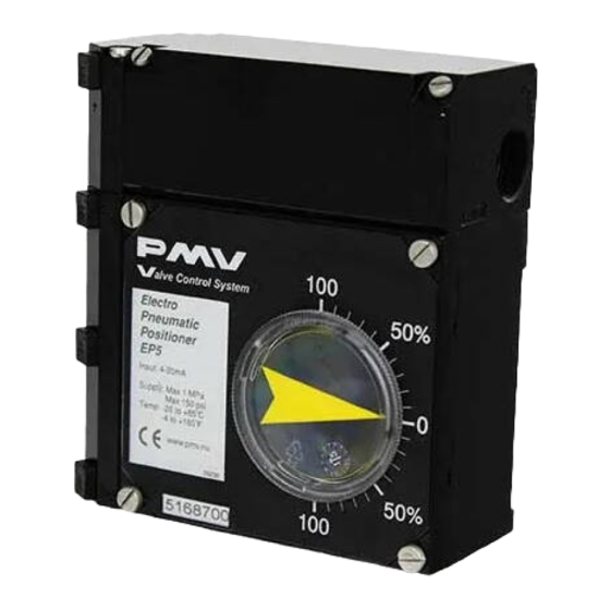
Introduction The P5 Valve Control System is a valve positioning system from PMV with a modular design concept. The base unit of the system is the pneumatic positioner, used in either single or double acting applications. P5 comes standard with built in dampers, a 5 mm high gain spool valve assembly, gauge ports and an O-ring sealed housing. -
Page 5: Storage Instructions, Storage Seal
Appropriate precautions should be taken to protect units while in storage. Warehouse storage Stored in original PMV shipping containers, units should be stored in an environmentally controlled area, i.e. clean, cool (15-26°C, 60-80°F) and dry, out of direct sunlight or weather exposure. - Page 6 P5/EP5 is supplied with all enclosure entry points sealed.The seal is only a storage seal, not to be used as seal when P5/EP5 is in operation. If Storage Seal is removed or damaged, make sure all open enclosure entry points are proper resealed before further shipping or storage.
-
Page 7: Function
Function The P5 operates on a force balance principal. Force is originated by the signal pressure transmitted through a diaphragm on to the balance arm. The opposing force is achieved through the feedback spring and is proportional to the position of the lower arm. The lower arm posi-... -
Page 8: Air Requirements
Installation P5 mounts on to the actuator using either the ISO F05 holes 4 and a PMV ISO mounting kit or by using the optional mounting adaptor and screws 5 to mount P5 on to existing PMV mounting kits. -
Page 9: Connections
When using gases other than air for supply – Please contact PMV. On EP5 (P5 with I/P unit installed) I/P unit is supplied with air from port S. Port I is automaticly sealed off and protected. No connection shall be made to this port. -
Page 10: Front Cover And The Indicator Cover
Front cover and indicator cover The front cover of P5 is secured to the pneumatic unit with four captured screws and sealed with an O-ring 1. The O-ring can be looped over notches 2 in the front cover to allow for drainage. -
Page 11: Span And Zero Adjustment
Always start calibration procedure by applying 0 % input signal, then adjusting zero. P5/EP5 is calibrated by turning thumb wheels 1 & 4. Arrows on arm 5 indicate turning direction of thumb wheels. -
Page 12: Indicator Adjustment
(Fig). Double acting actuators – adjust only OUTLET damper, set SUPPLY damper in minimum damping posi- tion. Single acting actuators – adjust both dampers for desired operation. – 12 – Manual P5/EP5 23740/98.10... -
Page 13: I/P Unit, Ep5
Caution: Do not operate the unit without filter and filterplug installed. Do not unscrew filterplug when the positioner is pressurized. Span and Zero for the I/P converter is factory set and can not be adjusted – 13 – Manual P5/EP5 23740/98.10... -
Page 14: How To Mount The I/P Unit
A gauge indicating output signal from the I/P converter can be installed in port P. Make sure that the filter plug is tightened before supply air is switched on (Fig 4 on page 13). – 14 – Manual P5/EP5 23740/98.10... -
Page 15: Maintenance
4 on the balance arm 5 is properly fitted in the groove on the spool 6. Check again to insure smooth operation of the assembly. To maintain original factory performance specifications, use only spool valve assemblies supplied by PMV – 15 – Manual P5/EP5 23740/98.10... -
Page 16: Diaphragm
Diaphragm If P5 is equipped with I/P unit (EP5), the I/P unit must be removed to access the diaphragm. Loosen screws 1 and remove the diaphragm cover 2. Loosen screw 3, diaphragm 4 and washers 5 can be removed. The diaphragm can after have being in use look wrinkled, this is fully normal due to the tension in it. -
Page 17: Feedback Spring
4 on the underside of the balance arm 5 is properly engaged into the groove 6 of the spool in the pilot valve. Tighten the two screws 3 holding the balance arm to the positioner. – 17 – Manual P5/EP5 23740/98.10... -
Page 18: Lower Arm
Always check O-rings when performing any work on the positioner and replace bad O-rings. A thin layer of silicon grease applied on the NBR (Black) O-rings prolongs their life. On Q (red) O-rings, use a non silicon based grease. – 18 – Manual P5/EP5 23740/98.10... -
Page 19: Filter Plug
1. Remove filter 3 and install a new into the filter plug . Check condition of O-ring 2 and filter compartment. If moisture is found, check upstream filters/oil-water separators. Moisture can cause I/P failure. Reinstall filter plug. – 19 – Manual P5/EP5 23740/98.10... -
Page 20: 14. Feedback Unit
14. Feedback Unit See feedback module instructions for connections and calibration. The P5 or EP5, Valve Control System, can easily be equipped with a Feedback unit, model F5. This unit will mount directly on top of the Pneumatic positio- ner replacing the positioner front cover. The O-ring located on the bottom of the Feedback unit, F5, will provide the same sealing or draining capabilities as the front cover. -
Page 21: Trouble Shooting
Trouble shooting Note: All PMV-positioners are serialized. Please note Signal change results in actuator running to end positions. — Check coupling between positioner and actuator. down, and provide the serial number when contacting — Check cam position and locking screw. -
Page 22: Exploded Drawing
Exploded Drawing 98.9 – 22 – Manual P5/EP5 23740/98.10... -
Page 23: Spare Part List
Plug NPT 1/8" 12047G Plug 1/8" G P5-Kxx 38-45, P5-Screws Screw set P5/EP5 75-80 46-53 P5-Seal NBR 1 O-ring set P5/EP5 81-83, 6 , 67, 70 Nitrile, NBR 46-53 P5-Seal Q O-ring set P5/EP5 81-83, 6 , 67, 70 Silicone, Q... - Page 24 Approvals E5-IS/EU – 24 – Manual P5/EP5 23740/98.10...
- Page 25 Approvals E5-EX/EU – 25 – Manual P5/EP5 23740/98.10...
- Page 26 Approvals E5-IS/US & E5-EX/US 1 – 26 – Manual P5/EP5 23740/98.10...
- Page 27 Approvals E5-IS/US & E5-EX/US 2 – 27 – Manual P5/EP5 23740/98.10...
-
Page 28: Approvals
Approvals EP5-IS (I/P-converter with white label) – 28 – Manual P5/EP5 23740/98.10... - Page 29 – 29 – Manual P5/EP5 23740/98.10...
- Page 30 – 30 – Manual P5/EP5 23740/98.10...
- Page 31 CENELEC – 31 – Manual P5/EP5 23740/98.10...
- Page 32 Tel: +1 281 292 7500 Fax: +46 (0) 54 52 14 42 Fax: +1 281 292 7760 E-mail: info@palmstiernas.se E-mail: pmvusa@pmvusa.com Internet: www.palmstiernas.se Internet: www.pmvusa.com (The information in this brochure is subject to change without notice.) Distributor – 32 – Manual P5/EP5 23740/98.10...
Need help?
Do you have a question about the P5 and is the answer not in the manual?
Questions and answers