
Summary of Contents for Brusa EVB1-400-40-HP
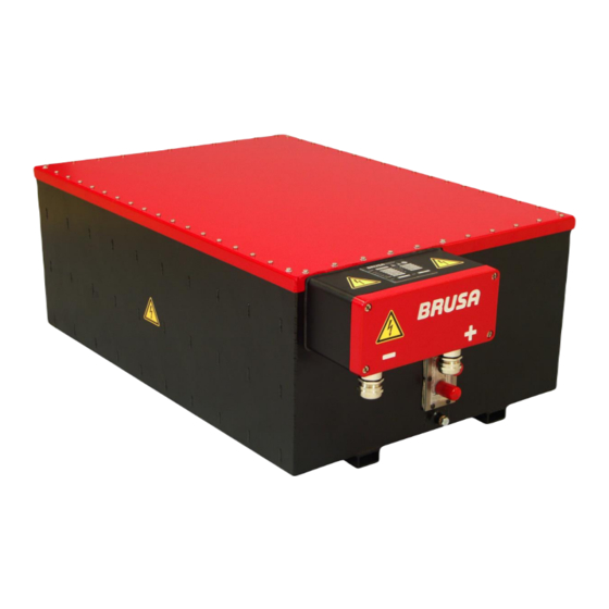
- Page 1 TECHNICAL DATA AND START-UP EVB1-400-40-HP EVB1-350-40-HP Translation of the original German operating instructions BRUSA Elektronik AG Neudorf 14 CH-9466 Sennwald +41 81 758 19 00 www.brusa.biz info@brusa.biz...
- Page 2 The content of this document may not be passed on to third parties without the written authorisation of the company BRUSA Elektronik AG - not even in extracts. Any technical information, drawings and photos used are copyrighted and failure to respect this constitutes a punishable offence!
- Page 3 ALIDITY This manual is valid only for the following devices: EVB1-400-40-A02-HP EVB1-350-40-A03-HP Decoding of the device designation is as follows: Technical data and start-up EVB1-350/400-40-HP...
-
Page 4: Table Of Contents
TABLE OF CONTENTS Foreword ..........................8 List of abbreviations ......................8 Safety and Warning Instructions..................9 Symbols and their meaning ......................9 Safety instructions and danger levels ..................10 Generally applicable safety measures ..................11 3.3.1 Safety instructions for cooling water systems ..............11 3.3.2 Safety instructions for handling and operation .............. - Page 5 Warning Instructions on the Battery ..................29 Basic Principle for Vehicle Installation ..................30 Safety measures for vehicle installation ..................31 6.5.1 Principle of operation Interlock ..................31 Basic Function Batterie EVB1-400/350-40-HP ................. 32 6.6.1 EVB1-400/350-40-HP Block Circuit Diagram ..............33 6.6.2 Pre-charging Voltage ......................
- Page 6 8.1.1 Charging (120 A) EVB1-400-40-HP ................... 54 8.1.2 Discharging (80A) EVB1-400-40-HP ................. 54 8.1.3 Discharging (320 A peak) EVB1-400-40-HP ..............55 8.1.4 Discharging (600 A peak) EVB1-400-40-HP ..............55 8.1.5 Charging (120 A) EVB1-350-40-HP ................... 56 Discharging (200 A) EVB1-350-40-HP ..................56 8.2.1...
- Page 7 10.6 Carrying Out Firmware Updates ....................85 CAN Matrix ........................89 11.1 CAN Signals / Messages ......................89 11.2 CAN Signals / Errorand Warning Messages ................91 Warranty .......................... 96 Instructions for Disposal ....................96 Index ..........................97 Technical data and start-up EVB1-350/400-40-HP...
-
Page 8: Foreword
Foreword Dear customer! With the BRUSA Batterie EVB1-400/350-40 you have obtained a very capable and versatile product. As this is a high performance electronic product, specialist knowledge is required for dealing with it as well as operating it! Read this manual - particularly the chapter Safety and Warning Instructions - carefully before you install the battery... -
Page 9: Safety And Warning Instructions
Safety and Warning Instructions In this chapter you will find safety instructions which apply to this device. These refer to assembly, start-up and running operation in the vehicle. Always read and observe these instructions in order to protect people's safety and lives and to avoid damage to the device! Symbols and their meaning Throughout this manual, some specific technical abbreviations are used. -
Page 10: Safety Instructions And Danger Levels
Safety instructions and danger levels DANGER This instruction warns against serious, irreversible risks of injury and in some cases death! Avoid these dangers by observing these instructions! WARNING This instruction warns against serious, irreversible risks of injury! Avoid these dangers by observing these instructions! CAUTION This instruction warns against serious, irreversible risks of injury! Avoid these dangers by observing these instructions! -
Page 11: Generally Applicable Safety Measures
Generally applicable safety measures The following safety measures have been developed based on the knowledge of the manufacturer. They are not complete, they can be supplemented by local and/or country-specific safety instructions and guidelines for accident prevention! The system integrator and/or distributor of the device must therefore supplement the present general safety instructions by country-specific and local guidelines. - Page 12 WARNING Overheating! Fire hazard! Always end the charging process after the given charging time is up even if the battery has not charged to 100%! A significant extension of the charging time can lead to overheating and then to the setting alight of the battery! ...
-
Page 13: Instructions For Storage And Transportation
In general the cell voltage should not fall below 2.6 V. If this is the case, the battery cannot be switched on again! In this case, a return to service can be carried out only by BRUSA experts! In general make sure that the SoC level is at around 50% before prolonged shut-down or storage of the battery! In the case of a complete discharge of the battery, we recommend switching off the battery and recharging it as soon as possible so that the threshold of <... -
Page 14: Safety Instructions For Electrical Systems
3.3.4 Safety instructions for electrical systems DANGER High voltage! Danger to life! Under no circumstances should you touch the HV wires and connections without ensuring that there is no voltage beforehand! The battery may only be connected by a qualified electrician! ... -
Page 15: Safety Installations / Power Limitations
Safety installations / power limitations 3.4.1 Temperature Monitoring (Derating) This security installation is the battery's self-protection. If a cell packet achieves a defined temperature threshold, this means a decrease in power (derating) to protect the battery from damage through overheating. The power will subsequently be reduced until the temperature falls back to the target range. - Page 16 Discharging 2.5°C before the actual derating, pre-derating begins and reducing the current from 600 A to 320 A (BATT_CurrentDischargeMax) at a rate of 128 A / °C. To inform you the CAN signal BMS_MODE_TP is emitted. 5°C before reaching the limit of temperature, the actual derating engages at a rate of 64A/°C reducing the current to 0 A (BATT_CurrentDischargeMax).
-
Page 17: Current Monitoring (Derating)
3.4.2 Current Monitoring (Derating) In the BMS the current is continually measured at 2.5 s intervals. This measurement can be communicated via CAN (BATT_Current_Act). Alongside this, a second measurement is taken continually at 125 ms intervals, this has a poorer resolution due to the shorter measurement time (6 A). This parallel measurement makes a very fast reaction / shut-down possible in the case of an overload. - Page 18 The current monitoring takes place in three steps: Step 1: Warning and Limit Reached As soon as the limit is reached or exceeded, the warning message or CAN signal MS_War_OverCurrentCharge or BMS_War_OverCurrentDischarge is emitted. In addition, the CAN signal BMS_MODE_CP is emitted. Step 2: Limit Reached, Peak Current Duration Exceeded ...
-
Page 19: Monitoring Of Cell Voltages
3.4.3 Monitoring of Cell Voltages In the BMS the two highest and the two lowest cell voltages are measured at intervals of 1 ms. These are relayed with the CAN signal CCU_V. Additionally every cell is measured in series at a frequency of around 1 kHz. The values measured are identified with an index and relayed one after another via CAN CCU_Cell. -
Page 20: Main Fuse Of The Battery
If this is the case, the battery must be sent back to be repaired! The replacement of the main fuse may only be carried out by the company BRUSA Elektronik AG because specialist knowledge is necessary for... -
Page 21: Contactors In The Bms
3.4.5 Contactors in the BMS The contactors in the BMS (HV+ and HV-) can be controlled by the customer, e.g. via terminal 15. The contactors disconnect the power supply to the HV cables. This prevents unwanted current flows. This way the vehicle is in a secure state. -
Page 22: General
Furthermore, you can find the specifications, usage information and a basic description of the battery and its specific components. The operation and safety instructions given must be strictly adhered to ensure the ongoing optimum functioning of the battery and to meet the guarantee requirements of the company BRUSA Elektronik AG. Scope of the Entire Documentation INFORMATION To start up the battery successfully, you will need the entire documentation as well as various types of software. -
Page 23: Delivery Contents
Delivery Contents NAME PIECES ILLUSTRATION 1. EVB1-400-40-HP battery including BMS 2. EVB1-350-40-HP battery including BMS 3. Magnetic core for EMI screening of the battery. 4. M8 cable lug without insulation respectively for: cable diameters of 50 mm and 35 mm 5. -
Page 24: Optional Delivery Contents
This manual has been produced under application and consideration of the EC guidelines, national laws and harmonised standards (EN) valid at the time of production relevant to the product Batterie EVB1-400/350-40-HP. Contact Information of the Manufacturer BRUSA Elektronik AG Neudorf 14 9466 Sennwald... -
Page 25: Use And Limits Of The Product
Use and Limits of the Product Proper Use The product Batterie EVB1-400/350-40-HP is designed for the following uses - bearing in mind the limits given in chapter Installation in a drive train for hybrid vehicles Installation in a drive train for electric vehicles ... -
Page 26: Improper Use
Under consideration of the proper uses named in chapter , the following limits are set for the operation of the product EVB1-400-40-HP or EVB1-350-40-HP. The product may not be used outside these limits. Operation outside the defined limits can lead to life-threatening situations. -
Page 27: About This Device
CAUTION It is not allowed to connect two or more batteries together in series! INSTRUCTION If you want to connect some batteries in parallel, please contact Brusa Elektronik AG (chapter 4.6) About This Device Technical Data BASIC ELECTRICAL DATA EVB1-350-40-HP EVB1-400-40-HP... -
Page 28: Technical Properties
THERMAL / COOLING SYSTEM EVB1-350-40-HP EVB1-400-40-HP UNIT Amount of coolant in device ca. 400 ca. 450 External diameter of cooling water connection pieces Recommended coolant temperature range at inlet + 5 to + 5 to °C + 20 + 20 Minimum coolant temperature at inlet °C... -
Page 29: Warning Instructions On The Battery
Warning signs are attached to the battery to warn the operator of possible dangers. Should one of these warning signs be missing or become illegible due to wear and tear, it must be renewed immediately! To get an original label, please contact BRUSA support at the manufacturer address given in chapter Technical data... -
Page 30: Basic Principle For Vehicle Installation
Basic Principle for Vehicle Installation INSTRUCTION The installation of a PDU is imperative, to protect the battery as well as any peripheral devices from voltage peaks, short-circuit situations and the serious damages resulting from these! The PDU should be safeguarded with a 300 A fuse. The battery has a 600 A DC semiconductor fuse. Technical data and start-up EVB1-350/400-40-HP... -
Page 31: Safety Measures For Vehicle Installation
This safety measure is a recommendation by the company BRUSA Elektronik AG and is understood as a basic requirement for the safe operation of electric vehicles! That’s a special assembling with parallel bus bars in the PDU. If it necessary please contact BRUSA Elektronik 6.5.1... -
Page 32: Basic Function Batterie Evb1-400/350-40-Hp
Basic Function Batterie EVB1-400/350-40-HP The battery EVB1-400/350-40-HP is designed and intended for fast and easy installation in electric vehicles. Integrated pre-charge switching and the driving via CAN bus enable simple and problem-free integration into an existing drive train. Through the integrated battery management system (BMS), the highest and lowest cell voltages are continually communicated via CAN. -
Page 33: Evb1-400/350-40-Hp Block Circuit Diagram
6.6.1 EVB1-400/350-40-HP Block Circuit Diagram Technical data and start-up EVB1-350/400-40-HP... -
Page 34: Pre-Charging Voltage
6.6.2 Pre-charging Voltage INFORMATION To avoid sparks when switching on, the connected loads are pre-charged with a 50 ohm PTC. For this process, three independent voltage measurements are used. The switching on of the battery (switching of the main contactors during pre-charging) is very easily heard and can therefore be used as a monitor. -
Page 35: Temperature Measurement / Temperature Monitoring
6.6.3 Temperature Measurement / Temperature Monitoring The temperature measurement takes place over one sensor per cell packet. In this, temperature is measured over 18 sensors in total. The highest (CCU_T_HIGH), the lowest (CCU_T_LOW) and the average temperature value (BATT_T_AVERAGE) can be emitted as an output value. Along with the voltage value, the temperature value per cell block is emitted with the relevant index in the message CCU_Cell (CCU_T). -
Page 36: Balancing
(this is equivalent to one balancing cycle). In connection with the BRUSA NLG5 charging device, this operation mode can be automatically activated. If using another charging device, this operation mode must be programmed accordingly first of all. -
Page 37: Auto-Reset Of The Ah Meter
6.6.5 Auto-reset of the Ah Meter This function ensures that, after the battery has been fully charged, the meter resets to 0 Ah (0% DoD). Without this function, the Ah meter would constantly shift because the battery loss could not be factored into the calculation, despite being picked up by the Ah meter. -
Page 38: Overview Of The Main Structural Components
Overview of the Main Structural Components HV connections Control connector Cooling water connections Square profile 40 x 20 x 3 mm Grounding screw GND Pressure balance membrane BMS (battery management system) Technical data and start-up EVB1-350/400-40-HP... -
Page 39: Dimensions And Installation Information
Dimensions and Installation Information CAUTION Damage to the Battery! The battery may only be installed horizontally (+/- 10°) (HV connections downwards)! A deviating installation position can lead to damages to the battery! Even if the battery has a high IP protection, install it well above the fording depth of the vehicle. ... -
Page 40: Dimensions
6.8.2 Dimensions 6.8.3 Installation Position INFORMATION In principle the battery should be installed in a horizontal position (underside of the battery in a horizontal direction). A maximum gradient of 10° degrees on each side is permitted here (see diagram). Installation positions deviating from this hold additional dangers and lead to damage to the battery! Larger inclination angles resulting from different driving situations (hill ascent, descent) have no negative influences because these are only in effect for short periods of time. -
Page 41: Regulation And Control System
Regulation and Control System INFORMATION In principle, the battery can be switched on independently by the vehicle control system via terminal 15 or via CAN bus. If the battery is switched on via terminal 15, the ID of the parameter Rx_CMD must be set to the value 0 in the PARAM software. -
Page 42: Control Via Terminal 15 With Driving Via Can
6.9.2 Control via Terminal 15 with Driving via CAN Technical data and start-up EVB1-350/400-40-HP... -
Page 43: Connections
Connections Circuit Connections You will find the required cable types and diameters in chapter 6.1 Technical Data High voltage+ (HV Plus) Ground (GND) chapter 7.2 Ground (GND) Control connector High voltage- (HV negative) chapter 7.2 Ground (GND) ø ø Cooling water outlet 15 mm Cooling water inlet 15 mm... -
Page 44: Ground (Gnd)
Ground (GND) INFORMATION The grounding screw (1) must be connected with the earth of the vehicle and/or testing bay. We generally recommend connecting the grounding wires of all drive components collectively to one ground pin. This minimises the risk of potential differences which can lead to the dysfunction of specific drive components! ... -
Page 45: Pin Assignment Of Control Plug (Device-Side)
Pin Assignment of Control Plug (Device-side) INFORMATION For a continuity check on the HV interlock pins (INT1, INT2), the multimeter must be set to the diode measurement setting because a bi-directional optocoupler is installed. 2. AUX Earth (minus wiring system, +12 V (plus wiring system, terminal 31) terminal 30) -
Page 46: Pin 1 Gnd
7.3.1 Pin 1 GND INFORMATION If the battery control signals are connected with other vehicle components, then the connection to the vehicle's ground must take place at this pin. Internal wiring Pin 1 GND housing Direct ground connection of the battery's control electronics. ... -
Page 47: Pin 3 En
7.3.3 Pin 3 EN INFORMATION To programme new firmware, pin 13 must be PRO = high! The voltage range for pin 3 EN = high is between 9 – 15 V. Internal wiring Pin 3 Schmitt Trigger If voltage is applied at pin 2 AUX and pin 3 is EN = high, this effects the start-up of the controller. ... -
Page 48: Pin 5 Pwmp / Pwm-Out
7.3.5 Pin 5 PWMP / PWM-out INFORMATION This PWM-controlled outlet may be charged with 4 A max. (at 12 V)! Programming is carried out using the software PARAM. Internal wiring Pin 5 15µH PWMP External Supply Via this pin, an external pump can be driven up to 4 A / 12 V, which is controlled by the BMS. ... -
Page 49: Pin 8 Apg, Pin 14 Cang, Pin 15 Rs232G
In this chapter, you will find all information regarding programming and the settings necessary for it. The firmware for the microprocessor can be downloaded over this interface (provided by BRUSA). Pin 13 PRO must be high for this. Technical data... -
Page 50: Pin 13 Pro
INSTRUCTION The programming of the wrong firmware can lead to the damage of the battery! So the programming may only be carried out after consultation with the company BRUSA Elektronik INFORMATION This pin is only activated for the programming of a new firmware (pin 13 PRO = high). Pin 3 EN must also be high for this. -
Page 51: Pin 16 Rfk1, Pin 17 Rfk2, Pin 18 Rfkc
7.3.10 Pin 16 RFK1, Pin 17 RFK2, Pin 18 RFKC INFORMATION These pins carry out redundant monitoring of each of the contactors from the outside via a switch in the contactor. This way, whether the contactors are open or closed can be constantly monitored. The signals can be analysed by the customer accordingly for this monitoring. -
Page 52: Pin 19 Int1, Pin 20 Int2
(pin 19 IL1 and pin 20 IL2) (alternatively via the BRUSA PDU254)! The shut-down of the battery must therefore take place through the feeding-in of an external signal (by the customer). As a result, the high voltage connections will be forced to disconnect immediately! The interlock switch is automatically activated as soon as the service cap is opened. -
Page 53: Pin 21 Naus
7.3.12 Pin 21 NAUS INFORMATION We recommend using a 15 A fuse for this pin on the 12 V battery (LV supply). The supply of both HV contactors takes place via this pin. The supply from pin 21 NAUS must temporarily provide 10 A to switch the contactors. ... -
Page 54: Profiles And Diagrams
The following profiles were determined under real environmental conditions. Room temperature = 25 °C Cooling water temperature flow = 15 °C Constant discharging of the battery 8.1.1 Charging (120 A) EVB1-400-40-HP CHARGING 120 A Current A Voltage V -100... -
Page 55: Discharging (320 A Peak) Evb1-400-40-Hp
8.1.3 Discharging (320 A peak) EVB1-400-40-HP DISCHARGING 320 A Current A Voltage V 0.5 1.5 Zeit in min 8.1.4 Discharging (600 A peak) EVB1-400-40-HP DISCHARGING 600 A Current A Voltage V Time in s Technical data and start-up EVB1-350/400-40-HP... -
Page 56: Charging (120 A) Evb1-350-40-Hp
8.1.5 Charging (120 A) EVB1-350-40-HP CHARGING 120 A Current A Voltage V -100 -120 -140 Zeit in min Discharging (200 A) EVB1-350-40-HP CHARGING 200 A -100 Current A Voltage V -150 -200 -250 Time in s 8.2.1 Discharging (80 A) EVB1-350-40-HP DISCHARGING 80 A Current A Voltage V... -
Page 57: Discharging (320 A Peak) Evb1-350-40-Hp
8.2.2 Discharging (320 A peak) EVB1-350-40-HP DISCHARGING 320 A Current A Voltage V Zeit in min 8.2.3 Discharging (600 A peak) EVB1-350-40-HP DISCHARGING 600 A Current A Voltage V Time in min Technical data and start-up EVB1-350/400-40-HP... -
Page 58: Temperature / Cooling System
Temperature / Cooling System INFORMATION The following profiles were determined under real environmental conditions. Room temperature = 25 °C Fan output 100% Constant discharging of the battery at 120 A (corresponds to around 48 kW output) 8.3.1 Cooling Behaviour at Cooling Water Inlet Temperature +5°C COOLING WATER INLET TEMPERATURE +5°C Temperature [°C]... -
Page 59: Cooling Behaviour At Cooling Water Inlet Temperature +25°C
8.3.3 Cooling Behaviour at Cooling Water Inlet Temperature +25°C COOLING WATER INLET TEMPERATURE +25°C Temperature [°C] Temperatur [C] 80 100 120 140 160 180 200 220 240 260 280 300 320 Strom [A] Current [A] Time in min 8.3.4 Cooling Behaviour without Active Cooling (Cooling Circuit Deactivated) COOLING CIRCUIT DEACTIVATED Temperature [°C] Temperatur [C]... -
Page 60: Installation / Initial Start-Up
Make visual checks on the packing material and the device itself in particular for damages before installation. Each device undergoes a strict quality and function test at BRUSA before distribution. However, we have no control over transportation routes which can sometimes take a long time and the shipping of our products. - Page 61 (1) for secure fit (locking (3) activated). 5. Install the CAN dongle. 6. Install the provided software PCANview. This software is recommended by BRUSA. Customer-specific software can of course be used as an alternative for this. 7. Install the provided software PARAM (PARAM.msi).
- Page 62 PROCEDURE STEP ILLUSTRATION / OTHER INFORMATION 10. Switch terminal 15 to high (e.g. switch on ignition key in vehicle). The BMS is switched on / activated. 11. Check the status and the current battery data of the BMS with the Param Software 12.
- Page 63 PROCEDURE STEP ILLUSTRATION / OTHER INFORMATION 17. Take the BMS covering (1) off. 18. Ensure that the HV contacts (1) are not live using a suitable multimeter. DANGER High voltage! Danger to life! The HV protector (2) is a safety installation and may under no circumstances be dismantled. The HV protector (2) protects the operator from touching the HV contacts! 19.
- Page 64 PROCEDURE STEP ILLUSTRATION / OTHER INFORMATION 20. Ensure that the washers (1) are positioned. 21. Set the magnetic cores (1) one behind another on the HV wiring (2). 22. Lead the prepared HV cable (1) through the cable gland (2) in the BMS. You must ensure that the washers are positioned on the HV contacts before you attach the cable lugs! (See procedure step 20)
- Page 65 PROCEDURE STEP ILLUSTRATION / OTHER INFORMATION 24. Position the union nut (1) manually. 25. Repeat procedure steps 22-24 on the second HV cable. 26. Position the M8 hexagonal nuts (1) on the HV connections (2) and tighten them. Torque = 5 Nm 27.
- Page 66 PROCEDURE STEP ILLUSTRATION / OTHER INFORMATION 28. Tighten the cable glands (1) and the union nuts (2) with the special key (3). 29. Remove the protective caps for the cooling water connection pieces (1) and connect the cooling water pumps with the hose clips. See chapter 7.1 Circuit Connections 30.
-
Page 67: Unpacking The Battery
INFORMATION The battery is now ready for operation and can be driven via terminal 15 or via the CAN, see chapter 6.9 Regulation and Control System The switching on of the battery (switching of the main contactors during pre-charging) is very easily heard and can therefore be used as a monitor. - Page 68 PROCEDURE STEP ILLUSTRATION / OTHER INFORMATION 6. Connect both tension belts (1) evenly with the hoisting device (2). 7. Hoist the battery (1) carefully by around 20 cm and check the secure position of both tension belts (2). 8. Hoist the battery out of the transportation box carefully and place the battery down on a secure and even surface.
-
Page 69: Building Hv Supply
Building HV Supply The building of the HV wiring must be carried out in accordance with the following instructions. Here it is important that no strands are damaged and that none stick out at the sides on the assembled cable. So check that the screw connections are correct for each completed cable and that the cable lug is fixed properly (pull test). - Page 70 PROCEDURE STEP ILLUSTRATION / OTHER INFORMATION 3. Lead the HV cable (1) through the union nut (2). Lead the HV cable (1) through the terminal insert (3). 4. Place the terminal insert (1) with the front edge flush with the cable insulation (2). 5.
- Page 71 If you have to reassembly the cable you have to use a new terminal insert. Otherwise it can cause a leakage. The terminal inserts can be ordered from BRUSA Elektronik AG or directly from hummel.com. NFORMATION The HV cable is now ready and can be connected to the BMS. Repeat the process with the second HV cable.
-
Page 72: Ventilating The Cooling System
Ventilating the Cooling System INSTRUCTION Air pockets in the cooling passage along with generally insufficient cooling of the battery lead to increased wear! Ensure that the cooling circuit is always fault-free. The cooling water must always be actively cooled to ensure the optimum operating temperature. The temperature of the cooling water should not surpass +20°C. -
Page 73: Operation
Operation 10.1 Reading CAN Parameters Debug Messages – Data Logging with PARAM 10.1.1 The Debug Messages Tab lists all registered CAN messages. They are listed in the XML file. The view can be used to see if all expected messages are on the bus. The PARAM tool can save a log file (MDF-format) of all registered messages. -
Page 74: Analysing Battery Data
You can enable auto logging in the Setup dialog. This will automatically start DAQ whenever the PARAM tool is started. The logging will start a new file when the given Max DAQ file size is reached. A date string is added to the filename. -
Page 75: Live View Of The Battery Data
10.2 Live View of the Battery Data With the corresponding software the battery data can be viewed in real time. For this we recommend for example the software PCAN-Explorer or PCANView. To be able to view the battery data, you must import the included file BMS_CAN1.dbc into the software you are using. -
Page 76: Changing The Can Parameters With Param
10.3 Changing the CAN Parameters with PARAM INFORMATION The installation of PARAM takes place in the course of the initial start-up, see chapter 9 Installation / Initial Start-up With the software PARAM all parameters can be viewed. There is the possibility of adapting individual parameters specifically. - Page 77 PROCEDURE STEP ILLUSTRATION / OTHER INFORMATION 5. Select the desired tab (here tab 3). 6. Change the desired parameters by typing in the column value (1). 7. To accept the changed data in the BMS, click the button Set (1). Technical data and start-up EVB1-350/400-40-HP...
- Page 78 PROCEDURE STEP ILLUSTRATION / OTHER INFORMATION 8. To save the changed values, scroll down to the bottom line Cal/Save CRC (1) and enter the value 1 in the column value. 9. To accept the changed data in the BMS, click the button Set (1) again.
- Page 79 PROCEDURE STEP ILLUSTRATION / OTHER INFORMATION 11. After successful configuration, end the software PARAM. INFORMATION To save the changed configuration the following steps must be carried out: 12. Carry out a reset at terminal 15 (switched positive). 13. Carry out a reset at terminal 30 (permanent positive). INFORMATION The changed parameters are now saved in the battery.
-
Page 80: Configurable Parameters
10.3.1 Configurable Parameters INFORMATION In this chapter, only the configurable parameters are listed. The complete CAN matrix is a part of the customer package. 1 GENERAL PARAMETERS NAME INIT DESCRIPTION DBG COM Master ID 0x400 ID of battery Tx message DBG COM Slave ID 0x401 ID of battery Tx message... - Page 81 12 NLG NAME INIT DESCRIPTION 12.8 Balancing 0.10 V Max. cell voltage difference (Max Cell Voltage – V_diff = V_min) 13 FAN&PUMP NAME INIT DESCRIPTION 13.1 Step1: temp off 25°C Step 1 switch-off temperature 13.2 Step1: temp on 30°C Step 1 switch-on-temperature 13.3 Step1: fan Step 1 fan power in percent...
-
Page 82: Charging With The Nlg513 Charger
Charging with the NLG513 Charger INFORMATION The following chapters are only relevant for the use of the battery EVB1 in combination with the BRUSA NLG513 charger. If you are using another charger then you can obtain this information from the manufacturer. 10.4.1... -
Page 83: Course Of A Charging Process
Course of a Charging Process INFORMATION By using the BRUSA NLG513 charger, along with being able to control via the CAN, you can also programme charging profiles using the software ChargeStar. The following charging profile provides an example of this. -
Page 84: Charging With The Nlg664 Charger
10.5 Charging with the NLG664 Charger The charging with the NLG664 is described in following state-diagram: Technical data and start-up EVB1-350/400-40-HP... -
Page 85: Carrying Out Firmware Updates
10.6 Carrying Out Firmware Updates INFORMATION The following requirements are necessary for the programming of the firmware: PC with Win2000, Win XP or Win 7 operating system RS232 interface RS232 connection cable (PC to EVB1 control plug) ... - Page 86 PROCEDURE STEP ILLUSTRATION / OTHER INFORMATION 7. Check the instructions in the dialogue box which appears. Press the OK button (1). The battery is now in Boot Mode. The querying of the standard battery settings starts. After Boot Mode is ended, the automatic reset of the battery is activated.
- Page 87 PROCEDURE STEP ILLUSTRATION / OTHER INFORMATION 10. Place the tick in the field use default (1). Press the Further button (2). 11. For Device Protection choose the Automatic setting (1). For Messaging choose the Advanced setting (2). Press the Finish button (3). 12.
- Page 88 PROCEDURE STEP ILLUSTRATION / OTHER INFORMATION 13. Press the Disconnect button (1). The connection to the battery is disconnected. With this Boot Mode is ended and a reset of the battery is activated. The battery is ready for operation after the reset. Alternatively, settings can be applied using Options –...
-
Page 89: Can Matrix
CAN Matrix 11.1 CAN Signals / Messages INFORMATION In this table you can find an overview of all CAN messages and the signals contained in them. This overview is a simplified depiction of the CAN matrix. NAME DESCRIPTION START BIT BIT LENGTH TRANSMISSION CYCLE TIME UNIT MODE... - Page 90 NAME DESCRIPTION START BIT BIT LENGTH TRANSMISSION CYCLE TIME UNIT MODE CODE (HEX) BMS_CMD_BALANCING_EN Clearance for balancing Cyclic BMS_CMD_RESET_AH Resetting AH meter (BCM_Ah Cyclic and BATT_DoD). Precondition: BMS_State = BMS_NLG_CHARGER BMS_CMD_FAN 0x0 = Automatic Cyclic 0x1 = FAN off 0x2 = FAN 10% 0x3 = FAN 20% 0x4 = FAN 30% 0x5 = FAN 40%...
-
Page 91: Can Signals / Errorand Warning Messages
11.2 CAN Signals / Errorand Warning Messages INFORMATION Error messages can basically be divided in the following categories: E (Error): Errors (generally lead to a shut-down of the system) TE (Temporary Error): Temporary errors (can generally be acknowledged) ... - Page 92 ERROR TYPE CAN SIGNAL DESCRIPTION CAUSE RESET CONDITION CONDITION ERROR CODE (HEX / DEC) BMS_Err_OverCharge One cell voltage is Highest cell voltage [Ri] > At new Kl_15 start up higher than permitted 4.15 V [6.4] 0x0080 and charging is continued it has been overcharged by more than 0.5 Ah [11.3] highest cell voltage [Ri] >...
- Page 93 ERROR TYPE CAN SIGNAL DESCRIPTION CAUSE RESET CONDITION CONDITION ERROR CODE (HEX / DEC) BMS_TErr_bit3 At new Kl_15 start up 0x1000 4096 BMS_TErr_bit4 At new Kl_15 start up 0x0800 2048 BMS_TErr_bit5 At new Kl_15 start up 0x0400 1024 BMS_TErr_VoltageDivCCU Total voltage BCM_U1 or BCM_U2 5000 ms At new Kl_15 start up...
- Page 94 ERROR TYPE CAN SIGNAL DESCRIPTION CAUSE RESET CONDITION CONDITION ERROR CODE (HEX / DEC) BMS_TErr_OverTemperature Temperature above CCU_T_HIGH > 46°C [10.3] At new Kl_15 start up the max. value OR BMS_State = 0x0002 I2 t of under -2 A [11.3] > BMS_SHUTDOWN 12000 A BMS_MODE_OTP = 0...
- Page 95 ERROR TYPE CAN SIGNAL DESCRIPTION CAUSE RESET CONDITION CONDITION ERROR CODE (HEX / DEC) BMS_War_CellVoltageDiff Too great a CCU_V_HIGH - Not set condition difference of the cell CCU_V_LOW > 400 mV* 0x0020 voltages 2/3[5.5] BMS_War_NLG NLG reports fault Report received from NLG Not set condition 0x0010 BMS_War_OverCurrentCharge Recommended...
-
Page 96: Warranty
Warranty The company BRUSA Elektronik AG provides a warranty period of 24 months after the date of purchase provided there are uniquely verifiable material and workmanship defects in the electronic components. For the individual cell packets a guarantee time of 12 months or 800 full cycles (depending on first start-up) is granted. -
Page 97: Index
Index Discharging 80 A ..............56 EVB1-400-40-HP Charging 120 A ..............54 Balancing ................... 36 Discharging 320 A peak ............55 Battery Discharging 600 A peak ............55 GND Connection ..............44 Discharging 80 A ..............54 Product-Lifespan Guidelines ..........12 Programming ................ - Page 98 Validity of the Manual..............3 Technical data and start-up EVB1-350/400-40-HP...
Need help?
Do you have a question about the EVB1-400-40-HP and is the answer not in the manual?
Questions and answers