Table of Contents
Advertisement
Quick Links
Advertisement
Table of Contents

Summary of Contents for Axeon S-150
- Page 1 Reverse Osmosis Process Controller User Manual Model S – 150...
- Page 2 This page intentionally left blank S – 150 Controller User Manual MKTF – 429-A 09/16...
-
Page 3: Table Of Contents
TABLE OF CONTENTS INTRODUCTION ......................... 6 SPECIFICATIONS ....................... 6 FRONT PANEL CONTROLS AND INDICATORS ..............7 INSTALLATION Physical Installation ......................8 Terminal Strip, Jumper and Adjustment Locations ............... 8 Power Wiring ........................8 Pump and Valve Relay Outputs ................... 8 Reverse Osmosis (RO) Pump Wiring ................... - Page 4 Operating Hours ......................... 18 Temperature ........................18 Warning Messages ......................18 Tank Full Operation ......................18 Tank Full Restart ........................ 18 Tank Full Override ......................19 Pressure Fault ........................19 Auto Reset .......................... 19 Alarm Silence ........................19 Pretreat ..........................19 Membrane Flush .........................
- Page 5 TDS / CONDUCTIVITY EXPANDER Installation / Wiring ......................24 Setpoints ..........................25 Operation ..........................25 Calibration .......................... 25 GENERAL WARRANTY ..................... 26 FIGURES AND TABLES Figure 1 – Front Panel Controls and Indicators ..............7 Figure 2 – Terminal Strip, Jumper Locations ............... 12 Figure 3 –...
-
Page 6: Introduction
INTRODUCTION The S – 150 Series controller is a state of the art control system for commercial and industrial reverse osmosis systems. The S – 150 Series controller combines features that have not previously been available in one compact unit. The S –... -
Page 7: Front Panel Controls And Indicators
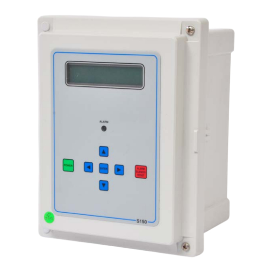
FRONT PANEL CONTROLS AND INDICATORS Figure 1 DISPLAY: Shows status of system. ALARM LAMP: Flashes when fault causes the RO system to shut down. On steady when a Setpoint is exceeded that does not cause the RO system to shut down. POWER KEY: Places controller in operating or standby mode. -
Page 8: Installation
INSTALLATION Physical Installation Mount the S – 150 Series controller in a convenient location on the RO equipment using the four mounting ears provided with the unit or the optional panel mounting bracket. NOTE: All terminals on the board are labeled. Terminal Strip, Jumper and Adjustment Locations Refer to Figure 2 for the location of all terminal strips and connectors. -
Page 9: Tds / Conductivity Cell Wiring
TDS / Conductivity Cell Wiring For accurate TDS / Conductivity readings, the cell should be installed in a tee fitting where a continuous flow of water passes over the cell and no air can be trapped around the cell. Refer to Figure 5 for example installation. -
Page 10: Pretreat Switch
Pretreat Switch In systems with pretreatment, a pretreat lockout switch can be connected to the pretreat input of P9. This switch should operate when the pretreatment device is out of service. NOTE: The output from the pretreatment device must be a dry contact and must not supply voltage. Tank Full Switch In systems with a single tank level switch for controlling the RO pump, the level switch connects to the tank full high input of P9. -
Page 11: Auxiliary Pump
Auxiliary Pump If the Expander Mode Setpoint is programmed to zero or one, Relay 1 operates as an auxiliary pump output. This output is energized when the tank low input is not active. This output will supply power or a contact closure determined by the connections L1 and L2 of the terminal strip P1. Boost Pump If the Expander Mode Setpoint is programmed to three or four, Relay 1 operates as a boost pump output. -
Page 12: Figure 2 - Terminal Strip, Jumper Locations
Terminal Strip, Jumper Locations Figure 2 S – 150 Controller User Manual MKTF – 429-A 08/16... -
Page 13: Figure 3 - Sample Wiring
Sample Wiring Figure 3 S – 150 Controller User Manual MKTF – 429-A 08/16... -
Page 14: Figure 4 - Expander Board Terminal Strip, Jumper Locations
Expander Board Terminal Strip, Jumper Locations Figure 4 TDS / Conductivity Cell Installation Figure 5 S – 150 Controller User Manual MKTF – 429-A 08/16... -
Page 15: Standard Setpoints
STANDARD SETPOINTS SETPOINT DESCRIPTION RANGE DEFAULT When this value is met or exceeded, the alarm lamp will light TDS / Conductivity 0 – 999 uS and high TDS / Conductivity will show on the display. To Limit or ppm disable, set to zero. TDS / Conductivity When the limit Setpoint is exceeded, no alarm will be given 0 –... -
Page 16: Displaying Or Changing Setpoints
TO DISPLAY OR CHANGE SETPOINTS Refer to Figure 1 for the location of the keys used to display or change the Setpoints and Figure 2 for the location of the write protect jumper, J3. For the unit to be able to accept a change in a Setpoint, the shorting jumper must be in the off position (center and left pins). -
Page 17: System Operation
SYSTEM OPERATION General Operation The unit has two modes of operation, a standby mode and an operating mode. In the standby mode, the unit is effectively off. All outputs are turned off and the display shows STANDBY. In the operating mode, the unit operates automatically. -
Page 18: Operating Hours
Operating Hours The current operating hours are shown on the bottom line. Temperature The current water temperature is shown on the bottom line after the operating hours. When the unit is offline because of a shutdown condition, the reading is replaced with ‘–––’. Warning Messages Warning messages are also shown on the second line. -
Page 19: Tank Full Override
Tank Full Override A timed tank full override can be initiated when the RO unit is shut down due to a tank full condition. Pressing the Alarm Silence/Reset key for three seconds during a tank full condition will enable the tank full override. -
Page 20: Membrane Flush
Membrane Flush If the Flush Type Setpoint is programmed to zero, flush is disabled. If membrane flush is desired, several types of flush are available. When the unit enters a flush cycle, the flush relay will activate. The flush cycle will last for the time programmed in the Flush Time Setpoint. Table 3 shows the value that must be programmed in the Flush Type Setpoint for each type of flush. -
Page 21: Flush Mode
Flush Mode The Flush Mode Setpoint can be used to control the operation of the inlet valve and RO pump during flush. Each can be independently programmed to operate during flush. Table 4 shows the values to program into the Flush Mode Setpoint to control the operation of the inlet and RO outputs during flush. FLUSH MODE RO PUMP INLET VALVE... -
Page 22: Tank Low
Tank Low When the tank low input has been active for five seconds, the auxiliary output will turn off. The alarm lamp will light and the TANK LOW warning message will show on the display. When the tank low condition clears, the TANK LOW 99 warning message is displayed. The number is the delay in minutes before the auxiliary relay will energize. -
Page 23: Troubleshooting
TROUBLESHOOTING CAUTION: Hazardous voltages are present when power is applied to the unit. Care should be taken when troubleshooting any of the input power or output circuits. When disconnecting or connecting any board or accessory, be sure power is turned off at the disconnect. Verify the programming of all Setpoints, Check the display and check the status of all lights and indicators. -
Page 24: Tds / Conductivity Expander
TDS / CONDUCTIVITY EXPANDER Installation / Wiring The TDS / Conductivity expander board allows a 2 TDS / Conductivity to be monitored and displayed by the S – 150 Series controller. The expander board is mounted on the main board to the left of the connector for the first cell. -
Page 25: Setpoints
Setpoints When the expander is installed, 3 additional Setpoints are provided to allow features of the expander to be changed. Refer to the Displaying or Changing Setpoints section of the manual on page 14 for information on changing the Setpoints. The additional Setpoints are listed below. SETPOINT DESCRIPTION RANGE... -
Page 26: General Warranty
General Warranty One–Year Limited Warranty The manufacturer (hereinafter “manufacturer”) provides a twelve (12) month limited warranty on the materials, workmanship, and performance of its own manufactured components, when installed and operated in accordance with the manufacturer’s recommended design and operating specifications. This warranty only applies to the original purchaser (the “Customer”) of each component (each “Product”) and commences from the date of purchase as stated on manufacturer’s original invoice. - Page 27 The Customer, at the Customer’s risk and expense, shall be responsible for returning such Product or component, only after obtaining a Return Goods Authorization (RGA) number from the manufacturer, arranging for freight prepaid, and in conformance with any special packaging and shipping instructions set forth on the operation documentation or RGA instructions, or as otherwise reasonably required, to the manufacturer’s address set forth below, together with (1) RGA number issued by the manufacturer at Customer’s request;...
Need help?
Do you have a question about the S-150 and is the answer not in the manual?
Questions and answers