
Summary of Contents for Pfaff Industrial 8312
- Page 1 8312 INSTRUCTION MANUAL This instruction manual applies to machines from serial number 10 030 037 and software version 3.1 onwards 296-12-18 975/002 Betriebsanleitung engl. 02.10...
- Page 2 The reprinting, copying or translation of PFAFF Instruction Manuals, whether in whole or in part, is only permitted with our previous authorization and with written reference to the source. PFAFF Industriesysteme und Maschinen AG Hans-Geiger-Str. 12 - IG Nord D-67661 Kaiserslautern...
-
Page 3: Table Of Contents
Contents Contents Page Safety..............................5 1.01 Directives ..............................5 1.02 General notes on safety.......................... 5 1.03 Safety symbols ............................6 1.04 Important notes for the user........................6 1.05 Operating and technical staff ........................7 1.05.01 Operating staff ............................7 1.05.02 Technical staff............................ - Page 4 Contents Contents Page Preparation ............................20 9.01 Adjusting the feed roller clearance (roller gap)..................20 9.02 Selecting the sealing mode and the pedal mode .................. 21 9.03 Secondary feed rollers .......................... 22 Sealing ..............................23 10.01 Sealing principle............................ 23 10.02 Sealing modes ............................
-
Page 5: Safety
Safety Safety 1.01 Directives This machine is constructed in accordance with the European regulations indicated in the conformity and manufacturer’s declarations. In addition to this instruction manual, please also observe all generally accepted, statutory and other legal requirements, including those of the user’s country, and the applicable environmental protection regulations! The valid regulations of the regional social insurance society for occupational accidents or other supervisory authorities are to be strictly adhered to! 1.02... -
Page 6: Safety Symbols
Safety 1.03 Safety symbols Danger! Special points to observe. Danger of hand injuries! Danger of burns from hot surface! Danger from electric voltage! 1.04 Important notes for the user This instruction manual is part of the equipment of the machine and must be available to the operating staff at all times. -
Page 7: Operating And Technical Staff
Safety 1.05 Operating and technical staff 1.05.01 Operating staff Operating staff are the persons responsible for setting up, operating and cleaning the machine and for removing any disturbances in the sewing area. The operating staff is obliged to observe the following points, and must: always observe the notes on safety in this instruction manual! avoid using any working methods which adversely affect the safety of the machine! avoid wearing loose-fitting clothing or jewelry such as necklaces or rings! -
Page 8: Danger
Safety 1.06 Danger When the machine is in operation, a work area of 1 m must be kept free in front of and behind the machine, so that access to the machine is possible at all times without difficulty. During operation do not place your hands in the area of feed roller 1 and sonotrode 2! Danger of fingers being drawn in and crushed! During operation do not touch sonotrode 2! Danger of burns from the heat-generating surface! -
Page 9: Proper Use
Proper use Proper use The PFAFF 8312 is used for continuous sealing of thin, thermoplastic materials, such as e.g. fleeces, felts, woven and knitted fabrics using ultrasonics. Any use of the machine which is not approved by the manufacturer shall be considered... -
Page 10: Specifications
Specifications Specifications Measures and weight Depth: 800 mm Width: 1200 mm Height: 1310 mm Weight: 127 kg Clearance Width: 410 mm Clearance under the rollers: max. 30 mm Connection data Operating voltage: 230 V ± 10 %, 50/60 Hz, 1-phase Max. -
Page 11: Disposal Of Machine
Disposal of machine Disposal of machine Proper disposal of the machine is the responsibility of the customer. The materials used for the machine are steel, aluminium, brass and various plastic materials. The electrical equipment comprises plastic materials and copper. The machine is to be disposed of according to the locally valid pollution control regulations; if necessary, a specialist is to be commissioned. -
Page 12: Transportation, Packing And Storage
Transportation, packing and storage Transportation, packing and storage 5.01 Transportation to customer’s premises The machines are delivered completely packed. 5.02 Transportation inside customer’s premises The manufacturer cannot be made liable for transportation inside the customer‘s premises nor to other operating locations. It must be ensured that the machines are only transported in an upright position. 5.03 Disposal of packing materials The packing materials of this machine comprise paper, cardboard and VCE fibre. -
Page 13: Explanation Of Symbols
Explanation of symbols Explanation of symbols In this instruction manual, work to be carried out or important information is accentuated by symbols. These symbols have the following meanings: Note, information Cleaning, care Maintenance, repairs, adjustment, service work (only to be carried out by technical staff) -
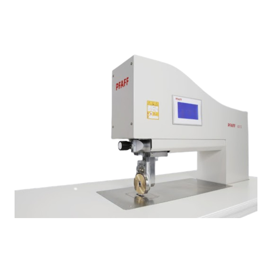
Page 14: Controls
Controls Controls 7.01 Summary of control elements Main switch 1, see section 8.03, p. 19 Control panel 2, see section 7.02, p. 15 Adjustment screw 3, see section 9.01, p. 20 Feed roller 4 (depicted comprising two feed wheels and a cutting wheel) Sonotrode 5 Secondary feed rollers 6, see section 9.03, p. -
Page 15: Control Panel
Controls 7.02 Control panel The control panel serves as both a display and an input device. Depending on the operating condition of the machine different menus will be shown. Within the menus all symbols and texts in rounded frames can be used as keys to activate functions or different menus. Activated functions are shown with inverted symbols. -
Page 16: Pedal
Controls Summary of the most frequently used symbols with related functions Increases displayed value (alternative to numeric input as shown above) Decreases displayed value (alternative to numeric input as shown above) Changes to operating mode input (main menu), see Chapter 11, p. 31 ff. Calls up service menu, see section 11.04, p. -
Page 17: Knee Switch (Optional)
Controls Kick pedal fully forward and hold: sealing will start and continue as long as pedal is being held. Release pedal: sealing stops. Kick pedal partially backward: feed roller will be lifted, the applicable gauge can be set in the feed roller parameters menu, see section 11.06, p. -
Page 18: Installation And Commissioning
Installation and commissioning Installation and commissioning After the machine has been unpacked, check it for any damages caused during transportation. If there is any damage, please notify the transport company and your local PFAFF agency. The machine must only be installed and commissioned by qualified personnel. All relevant safety regulations must be strictly adhered to! 8.01 Installation... -
Page 19: Commissioning
Installation and commissioning 8.02 Commissioning Clean the machine thoroughly if necessary. Check the machine, particularly its electrical wiring, for any damage. Have a qualified person check whether the motor can be driven with the existing power voltage. If there are any differences, the machine must definitely not be operated! The machine must only be connected to a suitably grounded socket! 8.03 Switching the machine on/off... -
Page 20: Preparation
Preparation Preparation All regulations and notes in this manual must be observed! Special attention must be paid to the safety regulations! All setting-up work must only be carried out by personnel with the appropriate training! 9.01 Adjusting the feed roller clearance (roller gap) Before starting to seal, the gap between feed roller and sonotrode must be adjusted manually –... -
Page 21: Selecting The Sealing Mode And The Pedal Mode
Preparation 9.02 Selecting the sealing mode and the pedal mode Before starting to seal, the operator chooses the sealing mode he is going to work in. Within any of the standard sealing modes he will also have to choose a pedal mode, either level mode or flip-flop mode. The pedal functions are described in section 7.03, p. -
Page 22: Secondary Feed Rollers
Preparation 9.03 Secondary feed rollers Secondary feed rollers can be mounted on both sides of the sonotrode. If needed they can be manually lifted, and will then assist in feeding the sealing material. By turning the handles – accessible from the front, below the sealing table –... -
Page 23: Sealing
The workpiece must be: - sealable (thermoplastic), - suitable for processing with the PFAFF 8312 with regard to thickness and properties and - clean in the seam area. The basic requirements on the machine are... -
Page 24: Standard Sealing With Specified Amplitude (Amplitude Sealing)
Sealing 10.02.01 Standard sealing with specified amplitude (amplitude sealing) While sealing in the amplitude sealing mode the operator may specify the sealing amplitude as well as the sealing speed and the sealing pressure. Base menu of the amplitude sealing mode (selecting the base menus see section 9.02, p. 21): The three frames in the middle of the control panel display the following sealing parameters: Sealing amplitude. -
Page 25: Standard Sealing With Specified Power (Power Sealing)
Sealing Further functions available in the amplitude sealing mode: Changes to basting mode, see section 10.02.05, p. 28 Formula number of the current sealing formula. For storing and recalling sealing formulas see section 10.03, p. 30. Changes to the main menu input, see Chapter 11, p. 31. 10.02.02 Standard sealing with specified power (power sealing) While sealing in the power sealing mode the operator may specify the sealing power as... - Page 26 Sealing After setting the sealing parameters the sealing can be controlled by using the pedal (pedal functions see section 7.03, p. 16) or by using the control panel: Feed roller will be lifted/lowered. Starts sealing Stops sealing (Symbol will be displayed as soon as the sealing has been started.) Further functions available in the power sealing mode: Changes to basting mode, see section 10.02.05, p.
-
Page 27: Dynamic Sealing With Specified Amplitude
Sealing 10.02.03 Dynamic sealing with specified amplitude In the dynamic sealing mode the operator may set a range for each of the sealing parameters. While operating, the machine will control the parameters within the given range in proportion to the pedal position. Base menu of the dynamic sealing mode with specified amplitude (selecting the base menus see section 9.02, p. -
Page 28: Dynamic Sealing With Specified Power
Sealing 10.02.04 Dynamic sealing with specified power In the dynamic sealing mode the operator may set a range for each of the sealing parameters. While operating, the machine will control the parameters within the given range in proportion to the pedal position. Base menu of the dynamic sealing mode with specified power (selecting the base menus see section 9.02, p. -
Page 29: Basting
Sealing 10.02.05 Basting In the basting mode sealing is performed point by point (without feed stroke) in accordance with specified parameters. The workpiece is fed manually by the operator between basting cycles. Switch on the machine. The machine will start in the base menu of the sealing mode last selected. Call up the basting mode. -
Page 30: Sealing Formulas
Sealing Further functions available in the basting mode: Feed roller will be lifted/lowered. Changes to that sealing mode from which the basting mode was called up before. With the knee switch (available as an accessory) a basting cycle can be set off at any time, without previously activating the basting mode in the control panel. -
Page 31: Input
Input Input The input mode contains the functions for displaying information, for machine adjustment and configuration, as well as for supporting service and adjustment work. 11.01 Main menu input Switch on the machine. Call up the main menu input. The following functions are available in the main menu input: Changes to the operating mode sealing. -
Page 32: Data Management
Input 11.02 Data management Using the data management menu, configuration data for the machine and sealing formulas can be transferred from the machine memory to a USB flash drive or vice versa. The USB port is located outside of the control box below the fan outlet. Any USB flash drive used must be formatted with FAT32. -
Page 33: Settings Menu
Input Further functions: Changes to the operating mode sealing. Changes to the main menu input. 11.03 Settings menu Besides selecting the sealing and pedal modes, described in section 9.02, p. 21, further machine settings can be carried out from this menu. Call up the main menu input. -
Page 34: Service Menu
Input 11.04 Service menu To prevent any damage to the machine caused by inappropriate settings in the service menu, access to the service menu is secured by a service PIN that will be disclosed to the proprietor by the PFAFF agency. The service PIN will be requested when first calling up the service menu. -
Page 35: Blocking The Feed Roller
Input 11.05 Blocking the feed roller This function is used to block the feed roller temporarily, e. g. to facilitate a roller change. If the blocking of the feed roller is released before the service work is completed, there is a danger of injury. -
Page 36: Setting Feed Roller Parameters
Input 11.06 Setting feed roller parameters In this menu the following parameters may be set: the feed roller diameter, the lifting gauge, the sealing delay and the back feed after sealing. Call up the main menu input. Call up the settings menu. Call up the feed roller parameters menu. -
Page 37: Setting The Neutral Point Of The Feed Roller
Input 11.07 Setting the neutral point of the feed roller In this menu the neutral point of the feed roller can be set, e. g. after changing the feed roller. Call up the main menu input. Call up the settings menu. Call up feed roller neutral point menu. -
Page 38: Pin Code Menu
Input 11.08 PIN code menu The PIN code protects some of the machine’s functions against unauthorized access. After switching on the machine, the PIN code will be requested as soon as any of the following protected functions is called up: - Data management - Sealing parameter input - Formula numbers... - Page 39 Input If the PIN code should be forgotten, the PIN code menu can be accessed by entering the service PIN instead. The service PIN is disclosed to the proprietor by the PFAFF agency. After the service PIN is entered, the service menu and all functions secured by the PIN code will be freely accessible until the machine is switched off.
-
Page 40: Adjusting The Clock Time
Input 11.09 Adjusting the clock time In this menu the clock time of the machine may be set, which will be shown in some of the menus in the right upper corner of the control panel. Call up the main menu input. Call up the settings menu. -
Page 41: Adjusting The Current Of The Drive Motors
Input 11.10 Adjusting the current of the drive motors To prevent damage to the machine, never operate the drive motors with more than 70 % current for an extended period of time. If the maximum torque of the drive motors is not required, sound emission, power consumption and waste heat can be reduced by lowering the current of the drive motors. -
Page 42: Setting The Machine Configuration
Input 11.11 Setting the machine configuration Configuration settings that do not comply with the actual equipment of the machine may cause damage to the machine! Changes in the configuration will only be necessary after components of the machine have been replaced by parts of different specification. Therefore settings in this menu may only be carried out by expert staff trained for this purpose. -
Page 43: Changing The Contrast Of The Control Panel Display
Input 11.12 Changing the contrast of the control panel display General information about the functionality of the control panel is given in section 7.02, p. 15. Switch on the machine. Call up the main menu input. Call up the service menu. Call up the contrast setting menu. -
Page 44: Rental Menu
Input 11.13 Rental menu On rented machines the rental period is displayed in this menu. The menu is also used for activating a renewal of the rental period. Call up the main menu input. Call up the service menu. Call up the rental menu. Calls up a display showing the CPU identification, the current date, the serial number and the end of the rental period. -
Page 45: Maintenance And Self Help
Maintenance and self help Maintenance and self help 12.01 Cleaning and care To always ensure best working results please observe the following instructions for cleaning and care. Always remove material residues sticking to the feed rollers and the sonotrode. Also remove particles of dust and fuzz that may accumulate in the proximity of the sonotrode. -
Page 46: Changing Feed Roller
Maintenance and self help 12.03 Changing feed roller To prevent injury while changing the feed roller, observe the directions in section 11.05 Blocking the feed roller, p. 35! To prevent damage to the machine the cutting wheel must be adjusted above the centerline of the sonotrode (see illustrations below). -
Page 47: Error Messages
Maintenance and self help 12.04 Error messages In case of a malfunction, an error message will be displayed in the control panel, consisting of an error number and an error parameter number. Please write down the displayed numbers in any case and keep them at hand while contacting your PFAFF agency. -
Page 48: Circuit Diagrams
Circuit diagrams Part 1 12.05 Circuit diagrams Circuit diagrams Part 1... - Page 49 Circuit diagrams Part 2 Circuit diagrams Part 2...
- Page 50 Circuit diagrams Part 3 Circuit diagrams Part 3...
- Page 51 Circuit diagrams Part 4 Circuit diagrams Part 4...
- Page 52 Circuit diagrams Part 5 Circuit diagrams Part 5...
- Page 53 Circuit diagrams Part 6 Circuit diagrams Part 6...
- Page 54 PFAFF Industriesysteme und Maschinen AG Hans-Geiger-Str. 12 - IG Nord D-67661 Kaiserslautern Telefon: +49 - 6301 3205 - 0 Telefax: +49 - 6301 3205 - 1386 E-mail: info@pfaff-industrial.com Gedruckt in der BRD / Printed in Germany / Imprimé en la R.F.A. / Impreso en la R.F.A...
Need help?
Do you have a question about the 8312 and is the answer not in the manual?
Questions and answers
what is error 8 parameter 0 on machine pfaff 8312-001