Table of Contents
Advertisement
Quick Links
ENGLISH
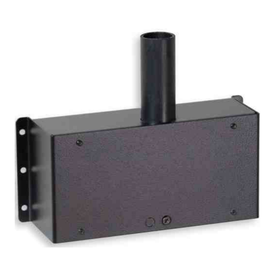
Art.265-10: Radio Receiver
for FS Scoreboards
General index
1. I
...........................................................1
NTRODUCTION
2. E
LECTRICAL POWER SUPPLY SYSTEM
3. S
ERIAL DATA CABLE SYSTEM
4. I
NSTALLING THE RECEIVER
4.1 Selecting the correct position.......................................2
4.2 Installing on wall..........................................................2
5. C
ONNECTING AND TESTING THE SCOREBOARD
1.
I
NTRODUCTION
This manual covers all aspects of installation and maintenance of the Radio Receiver for electronic FS series scoreboards; for
the Radio Receiver to function properly, it is important that it is installed correctly: please read the manual carefully before
attempting to install the Radio Receiver. The Command Console of the scoreboards must be equipped with a Radio
Transmitter.
2.
E
LECTRICAL POWER SUPPLY SYSTEM
Since every Radio Receiver is provided with a power supply cable and plug, we suggest that a power cord socket controlled
by an easily accessible switch be placed nearby. It is convenient to use the one provided with the various scoreboards.
3.
S
ERIAL DATA CABLE SYSTEM
The Radio Receiver has three identical serial data output ports (Fig. 8) to which the various electronic scoreboards can be
connected; to install the cables follow the directions below:
• do not pass the cable through the same ducts used for the electrical cables; this is to ensure safety, as well as to prevent
receiving electrical interference from motors, air-conditioners, uninterruptible power supplies, etc.;
• avoid placing the cable where it may be exposed to high temperatures, mechanical damage, or vandalism.
Seeing there is only one Radio Receiver, it is best to place it close to the cables connecting the various boards; examples of
configurations are shown in Fig. 1 and Fig. 2 below.
265-I01E Rx Radio FS Installation
.............................1
.......................................1
...........................................2
.................3
Art.265-10 - Radio Receiver for FS scoreboards
Installation and service manual
5.1 Connecting the Radio Receiver...................................3
5.2 Procedure of Associating the Radio Receivers...........3
5.3 Testing the Radio Receiver........................................3
6. M
AINTENANCE
6.1 Malfunctions................................................................4
6.2 Replacing the control board........................................4
6.3 Replacing the micro controller.....................................5
6.4 Replacing the power supply........................................5
Page 1 / 5
...........................................................3
FAVERO ELECTRONIC DESIGN
Advertisement
Table of Contents

Summary of Contents for Favero 265-10
- Page 1 5. C ....3 ONNECTING AND TESTING THE SCOREBOARD Art.265-10 - Radio Receiver for FS scoreboards NTRODUCTION This manual covers all aspects of installation and maintenance of the Radio Receiver for electronic FS series scoreboards; for the Radio Receiver to function properly, it is important that it is installed correctly: please read the manual carefully before attempting to install the Radio Receiver.
- Page 2 The various FS-24s scoreboard models displaying 24 second shot clocks require that the Radio Receiver be installed directly on the scoreboard’s rear panel (Fig. 7) by using the screws provided. FAVERO ELECTRONIC DESIGN 265-I01E Rx Radio FS Installation Page 2 / 5...
- Page 3 This chapter contains information on how to quickly resolve the main problems that may occur with the Radio Receiver over time. For problems with scoreboards, consult the relative installation manuals. If you have further problems that cannot be solved herein, please contact us. Page 3/ 5 265-I01E Rx Radio FS Installation FAVERO ELECTRONIC DESIGN...
- Page 4 Fig. 9: Lock nuts on the control board Fig. 10: Opening the top casing 3. On the radio module, extract the thin antenna cable from the connector; then with a screwdriver remove the power supply Page 4 / 5 FAVERO ELECTRONIC DESIGN 265-I01E Rx Radio FS Installation...
- Page 5 Insert and fasten the new power supply unit, then connect the power supply wires to the control board. Close the Receiver by replacing the top casing. Install on the wall and connect the cables. Page 5/ 5 265-I01E Rx Radio FS Installation FAVERO ELECTRONIC DESIGN...
Need help?
Do you have a question about the 265-10 and is the answer not in the manual?
Questions and answers