Table of Contents
Advertisement
Quick Links
Advertisement
Table of Contents

Summary of Contents for Mahlers Wasp G1
- Page 1 INSTRUCTION MANUAL Sweeper Wasp G1 Wasp G1 Version...
- Page 2 16-12-2009 Revision: Rev. date: 15-7-2011 Manufacturer: AB Mähler & Söner Hotingsvägen 40 S-880 51 Rossön, Sweden Telefon: +46 (0)624 – 203 50 Fax: +46 (0)624 – 200 50 http://www.mahlers.se/ Copyright: © AB Mähler & Söner 2 (40) Bruksanvisning Geting G1_B_EN...
- Page 3 Tommy Eliasson Approved by: Mähler & Söner Owner of manual: AB Mähler & Söner Hotingsvägen 40 S-880 51 Rossön Sweden +46 (0)624 – 203 50 Telephone: +46 (0)624 – 200 50 Fax: Copyright: © AB Mähler & Söner Information: http://www.mahlers.se/...
-
Page 4: Table Of Contents
Contents Foreword Safety precautions Warnings Symbols General safety precautions Safety precautions Technical description Function Technical data Working area Hydraulic system Alternative hydraulic operation Control panel Electrical system Chassis Hopper 3.10 Side brushes 3.11 Watering system Hitching up Description Hitching to towing vehicle Operation Checks before sweeping Adjusting sweeping width... -
Page 5: Foreword
1 Foreword This user manual contains a technical description, operating instructions, maintenance instructions and general safety precautions for working with or near the Geting G1 sweeper. The Geting G1 is designed and manufactured for commercial use and may only be used as a tool for sweeping up gravel, stones and refuse. The Geting G1 is produced in three versions, of which the base version has its own hydraulic system, and the hydraulic pump is connected to the power take-off on the towing vehicle. -
Page 6: Safety Precautions
2 Safety precautions 2.1 Warnings This manual uses warnings and symbols to clearly highlight information that relates to user safety and avoiding problems with the equipment. These symbols are used in this manual to indicate hazards that could cause personal injury. There are three different grades of warning: danger, warning and caution. -
Page 7: Symbols
2.2 Symbols Key to symbols that are used in this manual: Safety helmet A safety helmet must be worn to avoid head injuries. Safety footwear Safety footwear must be worn to prevent injury to feet and toes. Safety gloves Safety gloves must be worn to avoid hand injuries. Safety glasses Safety glasses must be worn to avoid eye injuries. -
Page 8: General Safety Precautions
2.3 General safety precautions Because the equipment has many different functions it is important to be aware of safety issues in the workplace and when using the equipment. The sweeper has many moving parts. It is hydraulically operated, and some sections of these instruction call for manual intervention, e.g. during maintenance and troubleshooting. -
Page 9: Noise Level
2.3.3 Clothing Protective clothing is essential. Always wear appropriate work clothing. Remember that loose or baggy clothing could create a hazard. Always wear: Safety footwear. Safety gloves. Safety glasses, especially when removing components of the hydraulic system, welding or using cutting equipment. 2.3.4 Noise level Hearing protection must be worn when hand tools are being used for maintenance or repairs. -
Page 10: Safety Precautions
2.3.7 Safety prior to maintenance Careful preparation is required before carrying out maintenance: Always mark out the area where maintenance is to be carried out. Switch off the machine/vehicle that the sweeper is hitched to. Check that the ignition switch and isolating switch are turned off. ... - Page 11 Never climb on to the machine or go near the side brushes when they are rotating. Before unhitching the sweeper, check that the support wheel is lowered and secured. Park the machine on level ground. The hydraulic system safety valves are sealed to prevent tampering and must not be adjusted.
-
Page 12: Technical Description
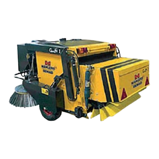
3 Technical description 3.1 Function The Geting G1 consists of a complete chassis (1) that is coupled by a tow hitch (2) to a towing vehicle. The base version has its own hydraulic system, and the hydraulic pump is connected to the power take-off on the towing vehicle. - Page 13 Figure 3: G1 sweeper, side view.
-
Page 14: Technical Data
Figure 4: G1 sweeper, top view. 3.2 Technical data Description Geting G1 Dimensions and weight Length 2425 mm Width 1350 mm Height 1100 mm Weight 900 kg Wheels Tyre size 5.00 x 8-10 ply Air pressure 6.5 bar (kg/cm Sweeping data Sweeping width 1600–1900 mm Side brushes... -
Page 15: Working Area
The rating plate and the CE plate are located on the left side of the machine, near the front of the lifting arm. These show the machine’s serial number and manufacturer’s number. Please state these numbers when ordering spare parts or making enquiries about servicing. -
Page 16: Control Panel
3.6 Control panel This is mounted inside the towing vehicle and used to operate the sweeper. A mounting plate with supply socket for the control panel is installed in the driver’s cab. Power is supplied to the socket on the mounting plate using wire with a cross-section of 2.5 mm run from the isolating switch on the towing vehicle. - Page 17 The knob on the right is used for emptying and closing the hopper. The first knob must be in the off position in order to use this function. Figure 5: Settings for G1 sweeper...
-
Page 18: Electrical System
Posn. Function Water on, brushes off Brushes on, water on Brushes on, water off Lower hopper Raise hopper Close hopper Empty hopper 3.7 Electrical system 3.7.1 Lighting The electrical system is rated for a 12-volt supply. Power is taken from the towing vehicle through a cable with 7-pin plug, which is connected to the matching socket on the towing vehicle. -
Page 19: Hopper
3.9 Hopper The hopper is supported on bushings in both lifting arms and has an opening at the rear where the roller housing is attached. Once the hopper has been raised it is tipped into the emptying position by means of a hydraulic cylinder on each lifting arm. To create as wide an opening as possible the stub shafts support lifting arms that raise the roller housing for emptying. -
Page 20: Watering System
3.11 Watering system If there is a risk of dust formation the swept area of the side brushes can be sprayed with water to bind the dust during sweeping. The water is drawn from a water tank, through a filter, by an electric water pump. -
Page 21: Hitching Up
4 Hitching up 4.1 Description The sweeper is supplied with the relevant installation drawings for installing and hitching up the equipment. Check that the information provided is appropriate for this product. Read through the instructions before starting work. 4.1.1 Vehicle equipment The towing vehicle must be suitably equipped before the sweeper can be attached: The towing vehicle must have a PTO rated for a maximum of 540... -
Page 22: Operation
5 Operation 5.1 Checks before sweeping Check the collector height to ensure it makes good contact with the road surface. Check that the rubber guides on the hopper make good contact with the ground. Check the adjustment of the side rollers. Check the pressure exerted by the sweeper roller. -
Page 23: Replacing The Side Brushes
Figure 6: Settings for G1 sweeper 5.4 Replacing the side brushes To replace the side brushes, first raise the side brushes and brush plates to their highest position. The brushes can then be unscrewed easily and new ones fitted. 5.5 Roller housing The roller housing consists of a frame with a motor housing on the right side plate that supports the roller’s hydraulic motor. -
Page 24: Replacing Brush Strips
5.6 Replacing brush strips Raise the hopper to a comfortable working height and empty it. Undo the gripper strips, slide out the brush strips from the side and replace them with new ones. Retighten the screws after driving for 10–15 minutes. NOTE Always wear gloves when replacing the brush strips, as the sheet metal profiles have sharp edges. -
Page 25: Sweeping
5.8 Sweeping Lower the hopper to sweeping position by turning the raise/lower knob on the control panel to the appropriate position. Start the brushes by turning the brush drive knob on the control panel. Accelerate the towing vehicle to the correct rpm. Normally the machine should be driven with a PTO speed of around 500 rpm. -
Page 26: Emptying Refuse
5.10 Emptying refuse Refuse can be emptied on to the ground or into a container. Repeat the emptying and closing action a few times to get rid of all the contents. Always raise the hopper before emptying so that the hopper and sweeper roller are clear of the chassis and the ground. -
Page 27: Maintenance
6 Maintenance Maintaining the sweeper and its various components can prevent breakdowns. Carrying out regular maintenance safeguards reliable operation and thus also improves safety. Always park the sweeper on level ground and switch it off before carrying out adjustments, repairs, cleaning and servicing. WARNING The sweeper must always be hitched to the towing vehicle before raising the hopper, as it could tip... -
Page 28: Lubrication
When repairs and maintenance are complete the entire working area and sweeper should be cleaned. WARNING Always wear safety gloves when handling oils and grease. Remember that hand tools can produce high noise levels. 6.1 Lubrication Lubricants The sweeper is supplied with Texaco Rando HDZ 32 hydraulic oil and Texaco Multifak EP2 grease. - Page 29 Weekly Location Measure Remarks Air spring Inspect Normally 4.0 bar. Measure with pressure gauge. Every 50 hours Location Measure Remarks Hydraulic oil level Check level Sight glass in oil tank Grease nipple for tow hitch Lubricate Multifak EP2 pivots Sweeper roller ball bearings Lubricate Multifak EP2 Every 100 hours...
-
Page 30: Lubrication Points
6.3 Lubrication points Figure 7: Lubrication points. Position Function Number of points Link bearing, lifting cylinder Bearing housing, sweeper roller Support wheel Wheel bearing Transport support Tow hitch pivots Universal joint 6.3.1 Changing hydraulic Run the oil until warm, around 40º C. Remove the drain plug and raise the hydraulic pump so that all the oil flows out. -
Page 31: Hydraulic System
6.4 Hydraulic system The hydraulic system must be depressurised before carrying out maintenance on it. Depressurising prevents oil from spraying out when a component is removed. WARNING Even low pressure hydraulic oil can cause eye injury if there is a leak or a component is removed. Make sure that hose connectors are kept clean at all times and their protective caps are fitted when they are disconnected. -
Page 32: At End Of Season
7 At end of season Storage The following steps are recommended before storing the sweeper at the end of the season: Wash the sweeper thoroughly, inside and outside, with warm water, preferably using a high-pressure washer. Any remaining dirt should be washed off with a suitable detergent. -
Page 33: Trouble-Shooting
8 Trouble- shooting Poor sweeping results or hopper filling slowly. Worn brush strips. Machine is not level. Check when hitched up on level ground. Pressure in air spring too high. Side brushes do not sweep refuse into centre, or throw it sideways. Side brushes incorrectly adjusted. -
Page 34: Reference Information
9 Reference information 9.1 Spare parts All parts that are replaced must be approved by the manufacturer. See the spare parts list. 9.2 Diagrams Hydraulic diagram Wiring diagram 101790 Wiring diagram for braked version (Austria) 9.3 Miscellaneous General terms of delivery are enclosed at the end of this document. Terms of warranty are enclosed at the end of this document. - Page 36 36 (40) Bruksanvisning Geting G1_B_EN...
- Page 38 38 (40) Bruksanvisning Geting G1_B_EN...
- Page 39 Your notes _________________________________________________ _________________________________________________ _________________________________________________ _________________________________________________ _________________________________________________ _________________________________________________ _________________________________________________ _________________________________________________ _________________________________________________ _________________________________________________ _________________________________________________ _________________________________________________ _________________________________________________ _________________________________________________ _________________________________________________...
- Page 40 R E D S K A P S SYS T E M F Ö R Ö K A D L Ö N S A M H E T AB Mähler & Söner Hotingsvägen 40, 880 51 Rossön Tel 0624 512 350 Fax 0624 200 50 Email info@mahlers.se...
Need help?
Do you have a question about the Wasp G1 and is the answer not in the manual?
Questions and answers