Table of Contents
Advertisement
Quick Links
Technical Product Documentation
Serial number:
Version:
Valid until:
Article number:
SPINNER WERKZEUGMASCHINENFABRIK GmbH
D-82054 Sauerlach, Rudolf-Diesel-Ring 24
Tel: +49 8104 / 803-0, Fax: +49 8104 / 803-19,
E-Mail: sales@spinnner-wzm.de; service@spinner-wzm.de
T o o l g r i n d e r S M 1 0 0
SM-2-12/02
61511
Advertisement
Table of Contents

Summary of Contents for Spinner SM100
- Page 1 T o o l g r i n d e r S M 1 0 0 Serial number: Version: SM-2-12/02 Valid until: Article number: 61511 SPINNER WERKZEUGMASCHINENFABRIK GmbH D-82054 Sauerlach, Rudolf-Diesel-Ring 24 Tel: +49 8104 / 803-0, Fax: +49 8104 / 803-19, E-Mail: sales@spinnner-wzm.de; service@spinner-wzm.de...
- Page 2 Technical product documentation Keep this Technical Product Documentation always at the machine! It must always be available! © SPINNER Werkzeugmaschinenfabrik GmbH SM-2-12/02...
-
Page 3: Table Of Contents
8.4 Grinding wheels.............................8-3 9 DRESSING THE GRINDING WHEEL................. 9-1 9.1 Operating elements ..........................9-2 9.2 Handling ..............................9-2 10 UNIVERSAL SWIVEL HOLDER ................10-1 10.1 Universal swivel holder ........................10-2 11 DIVIDING APPARATUS ..................11-1 11.1 Dividing apparatus..........................11-2 © SPINNER Werkzeugmaschinenfabrik GmbH SM-2-12/02... - Page 4 16.2 Other accessories (if not delivered with the machine) ...............16-3 17 CIRCUIT DIAGRAM....................17-1 17.1 Circuit diagram ..........................17-2 18 MICROSCOPE ....................... 18-1 18.1 Mikroskope............................18-2 18.1.1 Axial adjustment of the microscope ....................18-2 18.1.2 Radial adjustment of the microscope...................18-3 © SPINNER Werkzeugmaschinenfabrik GmbH SM-2-12/02...
- Page 5 Grinding the cutter .................................14-2 Grinding the radius ................................13-2 Grinding wheel flange (assembly)............................8-2 Grinding wheels ..................................8-3 Main connection ..................................5-2 Maintenance instructions .................................6-2 Operating elements ..................................4-2 Quick change unit ..................................7-2 Radius grinding..................................13-2 Universal swivel holder .................................10-2 Warnings and symbols ................................2-2 © SPINNER Werkzeugmaschinenfabrik GmbH SM-2-12/02...
- Page 6 Figure 14-8: Grinding the cutter .........................14-5 Figure 14-9: Handling............................14-6 Figure 14-10: Grinding the cutter relief......................14-6 Figure 14-11: Grinding the cutter relief......................14-7 Figure 14-12: Milling cutter ..........................14-7 Figure 15-1: Coolant unit............................15-2 Figure 15-2: Coolant hose ..........................15-3 © SPINNER Werkzeugmaschinenfabrik GmbH SM-2-12/02...
- Page 7 Technical product documentation Figure 18-1: Microscope ............................18-2 Figure 18-2: Axial adjustment of the microscope....................18-2 Figure 18-3: Radial adjustment of the microscope .....................18-3 © SPINNER Werkzeugmaschinenfabrik GmbH SM-2-12/02...
-
Page 8: Basic Information
Basic information Technical Product Documentation Machine type: Tool grinder SM100 Serial number: Version: SM-1-03/02 Valid until: Article number: 61511E 1 Basic information © SPINNER Werkzeugmaschinenfabrik GmbH SM-1-03/02... -
Page 9: Basic Information
− DIN EN 292 Part 1 and 2: Safety of machinery – Basic terminology, methodology (1991) The Spinner company reserves the right to make changes at any time to the product without prior notification. In addition, the information contained in this technical product documentation can be changed without prior notification. - Page 10 This technical product documentation contains copyright information protected by copyrights. All rights reserved. It is not permitted to reprint, photocopy or store this technical product documentation or any excerpt on an electronic storage medium without the expressed consent of the Spinner company. © Spinner Werkzeugmaschinenfabrik GmbH ©...
-
Page 11: Basic Safety Information
Basic safety information Technical Product Documentation Machine type: Tool grinder SM100 Serial number: Version: SM-2-12/02 Valid until: Article number: 61511E 2 Basic safety information © SPINNER Werkzeugmaschinenfabrik GmbH SM-2-12/02... -
Page 12: Warnings And Symbols
You may not make any changes or structural modifications to the machine or add equipment that may affect the safety of the machine without authorization from the supplier. This also applies to the installation and setup of safety equipment. © SPINNER Werkzeugmaschinenfabrik GmbH SM-2-12/02... -
Page 13: Application Limits
• Observe and maintain the prescribed setup, maintenance, and inspection tasks and schedules, including those specifications regarding the exchanging of parts/components, in the technical product documentation! These tasks may only be carried out by trained personnel! © SPINNER Werkzeugmaschinenfabrik GmbH SM-2-12/02... -
Page 14: Personnel Selection And Qualifications
• Machine and equipment parts on which inspection, maintenance and repair work must be done may not carry current or be under voltage when conducting such work! Switch off the corresponding equipment! © SPINNER Werkzeugmaschinenfabrik GmbH SM-2-12/02... -
Page 15: Oil, Grease And Other Chemical Substances
These dangers may only arise under certain circumstances or cannot be recognised as hazardous. We would especially like to point out that you should pay attention every time you use the machine. Inattention can lead to bodily injury and damaged equipment. © SPINNER Werkzeugmaschinenfabrik GmbH SM-2-12/02... -
Page 16: Description, Transportation, Installation Instructions
Description, Transportation, Installation instructions Technical Product Documentation Machine type: Tool grinder SM100 Serial number: Version: SM-2-12/02 Valid until: Article number: 61511E 3 Description, Transportation, Installation instructions © SPINNER Werkzeugmaschinenfabrik GmbH SM-2-12/02... -
Page 17: Ec Declaration Of Conformity
The following harmonised standards have been used: EN 294 EN 13218 EN 292 T1 EN 61000-6-2 EN 563 EN 61000-6-4 EN 954-1 EN 60204 T1 Sauerlach, December 2002 ............... Nicolaus Spinner, Dipl. Ing (FH) (Authorized signatory) © SPINNER Werkzeugmaschinenfabrik GmbH SM-2-12/02... -
Page 18: Application
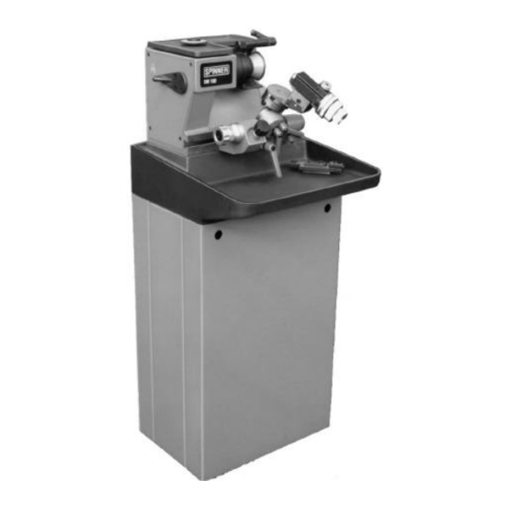
Description, Transportation, Installation instructions 3.2 Application The series SM100 is a small and compact grinding machine which can be used in a large number of applications in workshops. The machine serves only to produce and grind small cutting tools. The machine can be delivered as table machine or as machine with coolant tank and base. -
Page 19: Elements Of Delivery
Description, Transportation, Installation instructions 3.4 Elements of delivery 3.4.1 Basic equipment Table machine with base plate (basic machine SM100) 1 Technical manual 1 Socket screw wrench, 5mm, 6edges 1 Grease gun, 1 cable 1 socket wrench/box spanner for grinding wheel flange... -
Page 20: Transportation Of The Packed Machine
Lift the machine carefully from the pallet. THE MACHINE SHOULD SET DOWN WITH EXTREME CARE! MAKE SURE THAT THE TRANSPORTATION GOOD DOES NOT FALL! Weight: about 150kg Weight: about 50kg Figure 3-1: Transportation of the grinding machine © SPINNER Werkzeugmaschinenfabrik GmbH SM-2-12/02... -
Page 21: Installation Instruction
These can be moved with the assistance of an SW 24 spanner. Four support liners are already included in the machine delivery. The alignment of the table machine is not necessary. It is advisable to install the machine onto a workbench. Figure 3-2: Installation instruction © SPINNER Werkzeugmaschinenfabrik GmbH SM-2-12/02... -
Page 22: Operating Elements
Operating elements Technical Product Documentation Machine type: Tool grinder SM100 Serial number: Version: SM-2-12/02 Valid until: Article number: 61511E 4 Operating elements © SPINNER Werkzeugmaschinenfabrik GmbH SM-2-12/02... -
Page 23: Clamping Lever
D) Clamp for tilting movement 4.2 Operating elements A) Lever for changing the grinding wheel B) Adjusting screw for the infeed of the tool to the grinding wheel C) Stopper for tilting movement Figure 4-1: Operating elements © SPINNER Werkzeugmaschinenfabrik GmbH SM-2-12/02... -
Page 24: Device To Suck Off The Dust
Check regularly the function and dirt of the filters and rallying container of the suck off device. Check also if there are leaks. Clean and check the filters regularly according to the information of the manufacturer. © SPINNER Werkzeugmaschinenfabrik GmbH SM-2-12/02... -
Page 25: Figure 4-2: Device To Suck Off The Dust
Operating elements Figure 4-2: Device to suck off the dust © SPINNER Werkzeugmaschinenfabrik GmbH SM-2-12/02... -
Page 26: Electrical Connection
Electrical connection Technical Product Documentation Machine type: Tool grinder SM100 Serial number: Version: SM-1-03/02 Valid until: Article number: 61511E 5 Electrical connection © SPINNER Werkzeugmaschinenfabrik GmbH SM-1-03/02... -
Page 27: Electrical Connection
The coolant pump can be plugged into the lower socket. Overload circuit breaker: An overload circuit breaker for the spindle motor is located beneath the sockets. Machine lamp Coolant pump Figure 5-2: Sockets © SPINNER Werkzeugmaschinenfabrik GmbH SM-1-03/02... -
Page 28: Figure 5-3: Coolant Pump
The plug of the coolant pump has an integrated switch. When the coolant pomp is switched on it will only start when the grinding wheel starts. If the grinding wheel is switched off, the coolant pomp is also stopped. Figure 5-3: Coolant pump © SPINNER Werkzeugmaschinenfabrik GmbH SM-1-03/02... -
Page 29: Maintenance Instruction
Maintenance instruction Technical Product Documentation Machine type: Tool grinder SM100 Serial number: Version: SM-2-12/02 Valid until: Article number: 615011E 6 Maintenance instruction © SPINNER Werkzeugmaschinenfabrik GmbH SM-2-12/02... -
Page 30: Maintenance Instruction
A central lubrication nipple is located on the dividing apparatus. With the use of a suitable grease press, lubrication should be carried out approx. Every week depending on demand. For this, use a customary multi-purpose grease. © SPINNER Werkzeugmaschinenfabrik GmbH SM-2-12/02... -
Page 31: Figure 6-3: Lubricating The Dividing Apparatus
MACHINE MAY ONLY BE CARRIED OUT BY AN ELECTRICIAN! THERE IS DANGER! IF REPAIR WORK IS NECESSARY THE WORK ONLY MUST BE DONE BY A TECHNICAL ENGINEER FROM SPINNER OR FROM ANY OTHER COMPANY THAT IS AUTHORIZED BY SPINNER! © SPINNER Werkzeugmaschinenfabrik GmbH... -
Page 32: Quick Change Unit For Grinding Wheel
Quick change unit for grinding wheel Technical Product Documentation Machine type: Tool grinder SM100 Serial number: Version: SM-1-03/02 Valid until: Article number: 61511E 7 Quick change unit for grinding wheel © SPINNER Werkzeugmaschinenfabrik GmbH SM-1-03/02... - Page 33 It is not possible to start the grinding spindle again when the lever is in the open position. Figure 7-2: Quick change unit - lever “open“ © SPINNER Werkzeugmaschinenfabrik GmbH SM-1-03/02...
-
Page 34: Figure 7-3: Quick Change Unit - Changing The Grinding Wheel
90 degrees up to the stopper. After that, return the lever and lock the grinding wheel. Figure 7-3: Quick change unit - changing the grinding wheel © SPINNER Werkzeugmaschinenfabrik GmbH SM-1-03/02... -
Page 35: Assembly Of The Grinding Wheel Flange
Assembly of the grinding wheel flange Technical Product Documentation Machine type: Tool grinder SM100 Serial number: Version: SM-1-03/02 Valid until: Article number: 61511E 8 Assembly of the grinding wheel flange © SPINNER Werkzeugmaschinenfabrik GmbH SM-1-03/02... -
Page 36: Assembly Fittings
B and secure using the nut D. The premounted grinding wheel is to be placed into the holding device A along with the flange. Using the special wrench E, the flange is to be tightened firmly onto the grinding wheel. THERE IS DANGER IF THE FLANGE IS NOT FIRMLY TIGHTENED! © SPINNER Werkzeugmaschinenfabrik GmbH SM-1-03/02... -
Page 37: Grinding Wheels
Ceramic grinding wheels as well as diamond or borazon grinding wheels of many different shapes and sizes can be used, to the extent that the above mentioned criteria is fulfilled. Only the original grinding wheel flange may be used. Figure 8-3: Grinding wheels © SPINNER Werkzeugmaschinenfabrik GmbH SM-1-03/02... -
Page 38: Dressing The Grinding Wheel
Dressing the grinding wheel Technical Product Documentation Machine type: Tool grinder SM100 Serial number: Version: SM-1-03/02 Valid until: Article number: 61511E 9 Dressing the grinding wheel © SPINNER Werkzeugmaschinenfabrik GmbH SM-1-03/02... -
Page 39: Operating Elements
Start the grinding spindle and slowly move the dressing diamond past the grinding wheel. If necessary, repeat the dressing process with more infeed. © SPINNER Werkzeugmaschinenfabrik GmbH SM-1-03/02... -
Page 40: Figure 9-2: Handling
Dressing the grinding wheel Figure 9-2: Handling © SPINNER Werkzeugmaschinenfabrik GmbH SM-1-03/02... -
Page 41: Universal Swivel Holder
Universal swivel holder Technical Product Documentation Machine type: Tool grinder SM100 Serial number: Version: SM-1-03/02 Valid until: Article number: 61511E 10 Universal swivel holder © SPINNER Werkzeugmaschinenfabrik GmbH SM-1-03/02 10-1... -
Page 42: Universal Swivel Holder
D) Tilt and infeed movement Adjusting elements: E) Stopper “rotation“ F) Infeed for grinding G) Adjustment cross table H) Stopper tilting movement Figure 10-2: Cross table Cross table: I) Clamp “Top slide“ J) Micrometer screw K) Clamp “accessories“ © SPINNER Werkzeugmaschinenfabrik GmbH SM-1-03/02 10-2... -
Page 43: Cross Table
0.02mm. One revolution of the micrometer screw results in a lateral shifting of the cross table by 0.5mm. The range of adjustment amounts to 20mm. Figure 10-4: Fine adjustment © SPINNER Werkzeugmaschinenfabrik GmbH SM-1-03/02 10-3... -
Page 44: Adjustment Scale
The maximum turning angle amounts to 150 degrees on each side. Thus the universal swivel holder allows a total swivelling range around the rotary axis of a max. 300 degrees. Figure 10-6: Adjustment scale © SPINNER Werkzeugmaschinenfabrik GmbH SM-1-03/02 10-4... -
Page 45: Adjusting The Clearance Angle
Handling: The picture figures how to adjust the clearance angle. Using the clamping lever B the fixing device is opened. The universal swivel holder can be swivelled to the desired position for the clearance angle. After that, the clamping lever is to be tightened again. © SPINNER Werkzeugmaschinenfabrik GmbH SM-1-03/02 10-5... -
Page 46: Dividing Apparatus
Dividing apparatus Technical Product Documentation Machine type: Tool grinder SM100 Serial number: Version: SM-1-03/02 Valid until: Article number: 61511E 11 Dividing apparatus © SPINNER Werkzeugmaschinenfabrik GmbH SM-1-03/02 11-1... -
Page 47: Dividing Apparatus
0 degree up to 360 degrees. One graduation mark represents 2 degrees. The dividing apparatus can be mechanically locked every 30 degrees. For this purpose, a locking bolt E is mounted on the side. © SPINNER Werkzeugmaschinenfabrik GmbH SM-1-03/02 11-2... -
Page 48: Figure 11-3: Adjusting The Dividing Scale
If the locking bolt is pulled and then turned, the disengaged position is maintained. This is beneficial, for example, in case of cylindrical grinding when the collet chuck should be able to turn freely. © SPINNER Werkzeugmaschinenfabrik GmbH SM-1-03/02 11-3... -
Page 49: Figure 11-5: Indexing
Now the cutter can be ground to the center. To do this, it is advisable to hold the dividing apparatus with both hands and to perform the grinding process by moving back and forth. Figure 11-6: Grinding © SPINNER Werkzeugmaschinenfabrik GmbH SM-1-03/02 11-4... -
Page 50: Clamping Plate For Square Tools
Clamping plate for square tools Technical Product Documentation Machine type: Tool grinder SM100 Serial number: Version: SM-1-03/02 Valid until: Article number: 61511E 12 Clamping plate for square tools © SPINNER Werkzeugmaschinenfabrik GmbH SM-1-03/02 12-1... -
Page 51: Clamping Plate For Square Tools
The maximum height of the tool can amount to 25mm. Small bore holes are mounted in the base plate in which the cylindrical pins can be inserted. These pins serve as lateral stoppers for positioning of the tool. Figure 12-2: Clamping bracket of the camping plate © SPINNER Werkzeugmaschinenfabrik GmbH SM-1-03/02 12-2... -
Page 52: Figure 12-3: Stopper
Fine adjustments can be carried out using the integrated micrometer screw. This one has a scale of 0.02mm. One revolution of the micrometer screw results in a position change of 0.5mm. Figure 12-3: Stopper © SPINNER Werkzeugmaschinenfabrik GmbH SM-1-03/02 12-3... -
Page 53: Grinding The Radius
Grinding the radius Technical Product Documentation Machine type: Tool grinder SM100 Serial number: Version: SM-1-03/02 Valid until: Article number: 61511E 13 Grinding the radius © SPINNER Werkzeugmaschinenfabrik GmbH SM-1-03/02 13-1... -
Page 54: Grinding The Radius
With this the cross table is to be shifted by means of the micrometer screw. The left front corner of the tool is now located exactly in the rotational axis of the swivel holder. In this position the adjusted radius has the value 0. © SPINNER Werkzeugmaschinenfabrik GmbH SM-1-03/02 13-2... -
Page 55: Figure 13-3: Contacting The Tool
To do this, the clamp of the upper slide is to be loosened at first. A 5mm traverse means turning the micrometer screw by 10 revolutions. After that, the clamp of the upper slide is to be tightened again. © SPINNER Werkzeugmaschinenfabrik GmbH SM-1-03/02 13-3... -
Page 56: Figure 13-5: Adjusting The Radius
The tool is now situated in the correct position and grinding the radius can be started. Adjusting the clearance angle: Before starting to grind the radius, the clearance angle of e. g. 10 degrees must be adjusted. © SPINNER Werkzeugmaschinenfabrik GmbH SM-1-03/02 13-4... -
Page 57: Figure 13-6: Adjusting The Clearance Angle
It is advisable to open the central clamp of the universal swivel holder and to move the entire swivel holder to the correct position. Only in this case the infeed is done by the fine adjustment. © SPINNER Werkzeugmaschinenfabrik GmbH SM-1-03/02 13-5... -
Page 58: Radius Grinding
After that, the material removal process is repeated with a new turning angle . This is continued until the entire turning angle area is covered. After that the radius grinding is finished in one go. © SPINNER Werkzeugmaschinenfabrik GmbH SM-1-03/02 13-6... -
Page 59: Figure 13-10: Grinding The Radius
Different grinding wheels can be used for pre-grinding or finishing the grinding. Figure 13-11: Grinding the radius © SPINNER Werkzeugmaschinenfabrik GmbH SM-1-03/02 13-7... -
Page 60: Grinding The Cutter
Grinding the cutter Technical Product Documentation Machine type: Tool grinder SM100 Serial number: Version: SM-1-03/02 Valid until: Article number: 61511E 14 Grinding the cutter © SPINNER Werkzeugmaschinenfabrik GmbH SM-1-03/02 14-1... -
Page 61: Grinding The Cutter
By moving the swivel holder back and forth, material is removed by the grinding wheel. Continue fine infeed until the cutter has been halved. Figure 14-2: Halving the cutter © SPINNER Werkzeugmaschinenfabrik GmbH SM-1-03/02 14-2... -
Page 62: Cutter Grinding
This stopper can e, g, be set to 93 degrees. This corresponds to a clearance angle of 3 degrees at the face cutting edge. © SPINNER Werkzeugmaschinenfabrik GmbH SM-1-03/02 14-3... -
Page 63: Figure 14-5: Adjusting The Turning Angle
Clamp the turning angle at 30 degrees. Adjust the stopper for the insertion depth. After that, make contact to the grinding wheel and start the grinding process. Remove material by means of fine infeed during which time the swivel holder is to be moved back and forth. © SPINNER Werkzeugmaschinenfabrik GmbH SM-1-03/02 14-4... -
Page 64: Figure 14-7: Grinding The Cutter
The left hand carries out the back and forth movement for grinding while the right hand carries out the rotary movement. © SPINNER Werkzeugmaschinenfabrik GmbH SM-1-03/02 14-5... -
Page 65: Figure 14-9: Handling
This could happen if the dividing apparatus is turned too far. The scale of the dividing apparatus indicates the current position. © SPINNER Werkzeugmaschinenfabrik GmbH SM-1-03/02 14-6... -
Page 66: Figure 14-11: Grinding The Cutter Relief
The quick change unit for the grinding wheel offers the possibility of being able to use the optimal grinding wheel for every case of application. Figure 14-12: Milling cutter © SPINNER Werkzeugmaschinenfabrik GmbH SM-1-03/02 14-7... -
Page 67: Coolant Unit
Coolant unit Technical Product Documentation Machine type: Tool grinder SM100 Serial number: Version: SM-2-12/02 Valid until: Article number: 61511E 15 Coolant unit © SPINNER Werkzeugmaschinenfabrik GmbH SM-2-12/02 15-1... -
Page 68: Coolant Unit
A flexible plastic hose serves as the supply line for the cooling liquid. A ball-type spigot serves to regulate the coolant flow and to shutt off the line. There are drain holes in the machine pan which are connected to the coolant tank via a return line. © SPINNER Werkzeugmaschinenfabrik GmbH SM-2-12/02 15-2... -
Page 69: Recommended Coolant
Figure 15-2: Coolant hose 15.1.1 Recommended coolant Supplier Coolant Type of lubricant ACMOS ACMOSIT 64-20 Emulsion (water) (general use) Concentration 2,5% IT IS ABSOLUTELY NECESSARY TO MIND THE DATA SHEET OF THE USED COOLANT! © SPINNER Werkzeugmaschinenfabrik GmbH SM-2-12/02 15-3... -
Page 70: Accessories
Accessories Technical Product Documentation Machine type: Tool grinder SM100 Serial number: Version: SM-2-12/02 Valid until: Article number: 61511E 16 Accessories © SPINNER Werkzeugmaschinenfabrik GmbH SM-2-12/02 16-1... - Page 71 Collet type W25, 1.0< Ø <25.0mm, 0.5mm increasing Art.-No 10010+ Ø Collet type W355E, 1.0< Ø<20.0mm, 0.5mm increasing Art.-No 10008+ Ø Dressing diamond for ceramic wheels Art.-No 10013 Grinding wheel flange for quick change unit Art.-No 10014 © SPINNER Werkzeugmaschinenfabrik GmbH SM-2-12/02 16-2...
-
Page 72: Other Accessories (If Not Delivered With The Machine)
W20 up to 20mm 9) Single collets or sets 10) Collets with special design 11) Inserts W25 with MK1/2/3 12) Special clamping device The table machine can be extended with: 1) Base SM100 2) Tank with coolant supply ONLY ORIGINAL REPLACEMENT PARTS ACCESSORIES FROM SPINNER! ©... -
Page 73: Circuit Diagram
Circuit diagram Technical Product Documentation Machine type: Tool grinder SM100 Serial number: Version: SM-1-03/02 Valid until: Article number: 61511E 17 Circuit diagram © SPINNER Werkzeugmaschinenfabrik GmbH SM-1-03/02 17-1... -
Page 74: Circuit Diagram
Circuit diagram 17.1 Circuit diagram © SPINNER Werkzeugmaschinenfabrik GmbH SM-1-03/02 17-2... -
Page 75: Microscope
Microscope Technical Product Documentation Machine type: Tool grinder SM100 Serial number: Version: SM-1-03/02 Valid until: Article number: 61511E 18 Microscope © SPINNER Werkzeugmaschinenfabrik GmbH SM-1-03/02 18-1... -
Page 76: Mikroskope
B and is shifted to the right and left until the edge of the tool can be seen in the reticule of the microscope. Once the right position is reached the unit is attached by means of the lever 3. © SPINNER Werkzeugmaschinenfabrik GmbH SM-1-03/02 18-2... -
Page 77: Radial Adjustment Of The Microscope
The adjustment of the height of the microscope unit E is done by releasing lever 2 and then by shifting the microscope unit E up or down. The view is focused by turning the black adjustment ring F of the microscope unit E. © SPINNER Werkzeugmaschinenfabrik GmbH SM-1-03/02 18-3...
Need help?
Do you have a question about the SM100 and is the answer not in the manual?
Questions and answers