Table of Contents
Advertisement
Quick Links
See also:
User Manual
Advertisement
Table of Contents

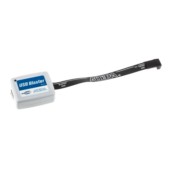
Summary of Contents for Altera USB-Blaster
- Page 1 USB-Blaster Download Cable User Guide 101 Innovation Drive San Jose, CA 95134 (408) 544-7000 http://www.altera.com Document Version: UG-USB81204-1.2 P25-10325-01 Document Date: December 2004...
- Page 2 Altera Corporation in the U.S. and other countries. All other product or service names are the property of their respective holders. Al- tera products are protected under numerous U.S.
-
Page 3: Table Of Contents
Software Requirements ........................1–2 Hardware Setup ............................. 1–2 Software Setup ............................1–3 Installing the USB-Blaster Driver ....................1–3 Setting Up the USB-Blaster Hardware in the Quartus II Software ........... 1–5 Chapter 2. USB-Blaster Specifications Overview ..............................2–1 USB-Blaster Connections ........................2–1 Voltage Requirements ........................ - Page 4 Contents Altera Corporation USB-Blaster Download Cable User Guide...
-
Page 5: Chapter 1. Setting Up The Usb-Blaster Download Cable
Device Support The USB-Blaster download cable allows you to program and configure ® Altera devices. Specifically, you can do the following: ■... -
Page 6: Software Requirements
■ Quartus II SignalTap II logic analyzer (standalone version) Hardware Setup This section describes how to install and set up the USB-Blaster download cable for device configuration or programming. For plug and header dimensions, pin names, and operating conditions, see Chapter 2, “USB-Blaster Specifications.”... -
Page 7: Software Setup
Installing the USB-Blaster Driver This section describes how to install the USB-Blaster driver. Before you begin the installation, verify the USB-Blaster driver is located in your directory: \<Quartus II system directory>\drivers\usb-blaster If the driver is not in your directory, download the USB-Blaster driver from the Altera web site: www.altera.com/support/software/drivers... - Page 8 Select Have Disk and browse to the location of the driver on your system: \<Quartus II system directory>\drivers\usb-blaster Click OK. Select Altera USB-Blaster and click Next to continue. 10. Click Next to install the driver. 11. Click Continue Anyway when the Hardware Installation warning appears.
-
Page 9: Setting Up The Usb-Blaster Hardware In The Quartus Ii Software
Setting Up the USB-Blaster Download Cable Setting Up the USB-Blaster Hardware in the Quartus II Software Use the following steps to set up the USB-Blaster hardware in the Quartus II software: Start the Quartus II software. Choose Programmer (Tools menu). - Page 10 Software Setup The USB-Blaster supports the Joint Test Action Group (JTAG), Passive Serial Programming, and Active Serial modes. Table 1–1. Programming Modes Mode Mode Description Joint Test Action Group Programs or configures all Altera devices (JTAG) supported by Quartus II software, excluding FLEX 6000.
-
Page 11: Chapter 2. Usb-Blaster Specifications
■ Operating conditions USB-Blaster The USB-Blaster cable has a USB universal plug that connects to the PC USB port, and a 10-pin female plug that connects to the circuit board. Connections Data is downloaded from the USB port on the PC through the USB- Blaster cable to the circuit board via the connections discussed in this section. -
Page 12: Cable-To-Board Connection
EPCS1 and EPCS4 devices 3.3 V Cable-to-Board Connection A standard USB cable connects to the USB port on the device. Figure 2–1 shows a block diagram of the USB-Blaster download cable. Figure 2–1. USB-Blaster Block Diagram USBVCC V CC 10-Pin... - Page 13 Dimensions are shown in inches. Spacing between pin centers is 0.1 inches. Table 2–2 identifies the 10-pin female plug pin names and the corresponding programming mode. Table 2–2. USB-Blaster Female Plug Signal Names & Programming Modes AS Mode PS Mode...
-
Page 14: Circuit Board Header Connection
USB-Blaster cable for the I/O drivers. Circuit Board Header Connection The circuit board's 10-pin male header, which connects to the USB-Blaster cable's 10-pin female plug, has two rows of five pins. These pins are connected to the device’s programming or configuration pins. Figure 2–3 shows the dimensions of a typical 10-pin male header. - Page 15 USB-Blaster Download Cable User Guide Table 2–4. USB-Blaster Cable Recommended Operating Conditions Symbol Parameter Conditions Unit Target supply voltage, 5.0-V operation 4.75 5.25 CC(TRGT) Target supply voltage, 3.3-V operation Target supply voltage, 2.5-V operation 2.375 2.625 Target supply voltage, 1.8-V operation 1.71...
-
Page 16: References
References References For more information on configuration and in-system programmability (ISP), see the following sources: ■ AN 39: IEEE 1149.1 (JTAG) Boundary-Scan Testing in Altera Devices ■ AN 95: In-System Programmability in MAX Devices ■ AN 250: Configuring Cyclone FPGAs ■... -
Page 17: Revision History
(7:00 a.m. to 5:00 p.m. Pacific Time) (7:00 a.m. to 5:00 p.m. Pacific Time) FTP site ftp.altera.com ftp.altera.com Note to table: You can also contact your local Altera sales office or sales representative. Altera Corporation 2–7 December 2004 USB-Blaster Download Cable User Guide... - Page 18 How to Contact Altera 2–8 Altera Corporation USB-Blaster Download Cable User Guide December 2004...


Need help?
Do you have a question about the USB-Blaster and is the answer not in the manual?
Questions and answers