Table of Contents
Advertisement
Available languages
Available languages
Quick Links
Advertisement
Chapters
Table of Contents

Summary of Contents for OVERMOUNT EM-PLA
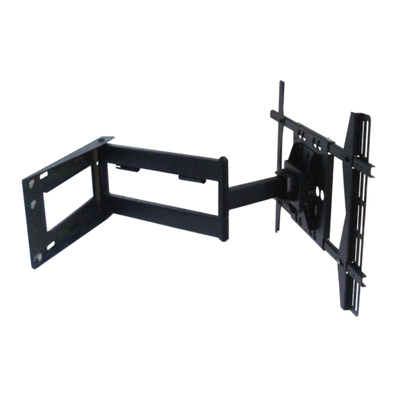
- Page 1 EM-PLA/PLAB INSTALLATION GUIDE Large Universal Cantilever Mount Features • Designed for 40"-58" Flat Panels • Maximum weight capacity up to 125 lbs • VESA compliant • Lift and Lock for easy installation • Integrated cable management • CUL Approved...
-
Page 2: Table Of Contents
Improper installation may cause serious injury and/or damage. It is recommended that a qualified contractor install the EM-PLA / EM-PLAB. • Make sure that the wall you plan to use will safely support four times the combined weight of the mounted equipment, including its accessories. -
Page 3: Installation Tools
Q Wall anchor Step 1: Determine the Mounting Location To provide maximum viewing flexibility, the EM-PLA mount is capable of a wide range of motion. This allows the plasma/LCD unit to be put in almost any position. When selecting the mounting location make sure there is adequate space on all sides of the panel to allow for full range articulation of the bracket. -
Page 4: Installation Template
3c Cinder Block Step 3a: Mounting to Wooden Studs The EM-PLA can be mounted onto two wooden studs, with center to center distances between 15" and 17" (38-43 mm). Using an electronic stud finder (Fig.2), locate the center of the two wooden studs at the Fig.2... - Page 5 Step 3b: Mounting to Concrete/Masonry Hammer Gently WARNING • NEVER drill into mortar joints! Fig.3 • Concrete must be 2000 PSI density minimum. Push in The wall plate can be mounted directly to concrete/masonry walls. Remove the tape strip from the back of the template, and place the template in the desired location. Using a bubble/laser level, align the template and then press the adhesive backing to the wall which will hold the guide in place.
-
Page 6: Mounting To The Wall
Note : Depending upon the roughness of the surface, you may need to hold the template in place with tape. Using a 1/2" (13 mm) drill bit, drill 6 mounting holes 31/8" (80 mm) deep into the cinder block surface. Drill through the mounting hole cut-out sections of the template. Carefully remove the template from the wall and discard. -
Page 7: Selecting The Mounting Hardware
Step 5: Assemble the Adapter Plate M6 Screw Metal Washer Attach the adapter panel to the adapter bars using four screws (¢6*¢10*1.2) and four metal washers (Fig.5.1.). Adapter Attach the adapter brackets to the adapter bars using four Adapter Panel screws and four metal washers (Fig.5.2). - Page 8 The spacers may be used individually,or may be snapped together to create one large stacked spacer.The spacers have been designed to snap directly into the mounting rail for ease in handling, and also include two different mounting holes to manage the various screw sizes.
-
Page 9: Using Cable Management
With all cables in place, pull the display in and out to be certain that the arm assembly moves freely, without stretching or damaging the cables. Step 10: Adjusting the Display The EM-PLA provides a wide range of adjustment possibilities to suit your environment. Roll Control Horizontal leveling of the flat panel display. - Page 10 Use care when moving the display to ensure that cables do not become stretched or pinched. Fig.20 Maintaining the EM-PLA The arm assembly and wall plate may be cleaned with a soft sponge and mild solution of soap and water.
- Page 11 GUIDE D'INSTALLATION EM-PLA/PLAB Support mural universel grand format avec bras d'extension Caractéristiques • Conçu pour les écrans plats de 40 po à 58 po • Peut supporter un poids maximal de 125 lb • Conforme au normes VESA • Installation facile par soulèvement et verrouillage •...
- Page 12 • Une installation inadéquate peut entraîner des dommages et des blessures graves. L'installation du EM-PLA / EM-PLAB par un technicien qualifié est recommandée. • Assurez-vous que le mur choisi peut supporter quatre fois le poids combiné de l'équipement monté de façon sécuritaire, incluant ses accessoires.
-
Page 13: Outils Nécessaires À L'installation
Q Ancrage mural Étape 1 : Choix de l'emplacement pour le montage Afin d'offrir un maximum de souplesse pour la visualisation, le support EM-PLA offre une grande latitude d'articulation. Cela permet à l'écran plasma/ACL d'être placé dans presque n'importe quelle position. -
Page 14: Guide D'installation
3c Bloc de cendre Étape 3a : Montage sur montant de bois Le support EM-PLA peut être monté sur deux montants de bois dont la distance d'un centre à l'autre de ceux-ci se situe entre 15" et 17" (38-43 mm). - Page 15 Étape 3b: Montage sur béton/maçonnerie Hammer Frappez AVERTISSEMENT Gently légèrement • Ne percez JAMAIS dans un joint de mortier! Fig.3 • Le béton doit être d'une densité minimale de 2000 psi. Poussez Push in La plaque murale peut être montée directement sur les murs de béton/maçonnerie. Retirez la bande protectrice à...
-
Page 16: Montage Au Mur
Remarque: selon la texture de la surface, il est possible que vous deviez utilisez un ruban adhésif pour maintenir le guide en place. À l'aide d'un foret de 1/2" (13 mm), percez 6 trous de montage d'une profondeur de 3 1/8" (80 mm) dans le mur de blocs de cendre. -
Page 17: Assemblage De La Plaque Adaptatrice
Étape 5 : Assemblage de la plaque adaptatrice Fixez le panneau d'adaptation aux barres d'adaptation au moyen des quatre vis et des quatre rondelles métalliques (Fig. 5.1). Rondelle métallique pour vis M6 (¢6*¢10*1,2) Fixez les supports d'adaptation aux barres d'adaptation au moyen des quatre vis et des quatre rondelles métalliques (Fig. -
Page 18: Fixation De L'écran
Ces cales d'espacement peuvent être utilisées seules ou peuvent être superposées pour créer une cale d'espacement grand format. Les cales d'espacement ont été conçues afin d'être pressées directement sur le rail de montage pour faciliter la manipulation et comprennent également deux trous de montages différents pour convenir aux vis de diverses tailles. De manière générale, la cale d'espacement de 5/8"... -
Page 19: Utilisation Du Range-Câbles
Étape 10 : Ajustement de l’écran Le support EM-PLA peut s'ajuster d'une multitude de façons pour convenir à votre environnement. Contrôle du niveau: mise à niveau horizontale de l'écran plat. Saisissez les bords latéraux de l'écran et faites-le pivoter vers le haut ou vers le bas jusqu'à ce qu'il soit au niveau (Fig. -
Page 20: Entretien De L'unité
Rentrer l'écran plat: positionnement de l'écran contre le mur. Remarque: prenez garde lors du déplacement de l'écran à ce que les câbles ne soient pas tendus ou écrasés. Entretien du support EM-PLA Fig.19 Le bras et la plaque murale peuvent être nettoyés à l'aide d'une éponge non abrasive et d'une solution douce faite d'eau et de...
Need help?
Do you have a question about the EM-PLA and is the answer not in the manual?
Questions and answers