Sign In
Upload
Download
Table of Contents
Contents
Add to my manuals
Delete from my manuals
Share
URL of this page:
HTML Link:
Bookmark this page
Add
Manual will be automatically added to "My Manuals"
Print this page
×
Bookmark added
×
Added to my manuals
Manuals
Brands
ARRI Manuals
Extender
WVT-1
User manual
ARRI WVT-1 User Manual
Wireless video transmitter & receiver
Hide thumbs
1
2
3
4
5
Table Of Contents
6
7
8
9
10
11
12
13
14
15
16
17
18
19
20
21
22
23
24
25
26
27
28
29
30
31
32
33
34
35
36
37
38
39
40
41
42
43
44
45
46
47
48
49
50
51
52
53
page
of
53
Go
/
53
Contents
Table of Contents
Troubleshooting
Bookmarks
Table of Contents
Table of Contents
2 For Your Safety
3 Audience and Intended Use
4 Introduction
5 WVT-1 Layout
6 WVR-1 Layout
7 WVR-1S Layout
8 Getting Started
Preparation
Operation
Pairing ALEXA LF or ALEXA SXT W to an ARRI WVS Receiver
Pairing WVT-1 to an ARRI WVS Receiver
Pairing Notes
OSD Messages
Status Leds
Sample Setups
9 Supported Resolutions
10 Supported Frequencies
11 Software Update
12 Troubleshooting
13 Appendix
Compatibility
Pinouts
Part Numbers
Specifications WVT-1
Specifications WVR-1
Specifications WVR-1S
Dimensions and Weight WVT-1
Dimensions and Weight WVR-1
Dimensions and Weight WVR-1S
Radio System
1Antenna Connector
2Color Coding
3Setting the Region of the Wireless Video Function
Service Contacts
International Declarations
Advertisement
Quick Links
1
Wvt-1 Layout
2
Wvr-1 Layout
3
Pairing Alexa Lf or Alexa Sxt W to an Arri Wvs Receiver
4
Pairing Wvt-1 to an Arri Wvs Receiver
Download this manual
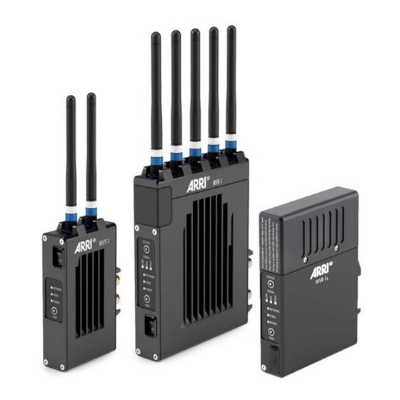
WVT-1, WVR-1 & WVR-1s
WVT-1, WVR-1 & WVR-1s
Wireless Video Transmitter & Receiver
Wireless Video Transmitter & Receiver
U S E R M A N U A L
U S E R M A N U A L
15th May 2019
15th May 2019
Table of
Contents
Previous
Page
Next
Page
1
2
3
4
5
Advertisement
Table of Contents
Need help?
Do you have a question about the WVT-1 and is the answer not in the manual?
Ask a question
Questions and answers
Related Manuals for ARRI WVT-1
Extender ARRI WVR-1 User Manual
Wireless video transmitter & receiver (53 pages)
Extender ARRI WVR-1s User Manual
Wireless video transmitter & receiver (53 pages)
Extender ARRI EB 4000 Operating Instructions Manual
Electronic ballast. booster. (15 pages)
This manual is also suitable for:
Wvr-1
Wvr-1s
Table of Contents
Print
Rename the bookmark
Delete bookmark?
Delete from my manuals?
Login
Sign In
OR
Sign in with Facebook
Sign in with Google
Upload manual
Upload from disk
Upload from URL


Need help?
Do you have a question about the WVT-1 and is the answer not in the manual?
Questions and answers