Table of Contents
Advertisement
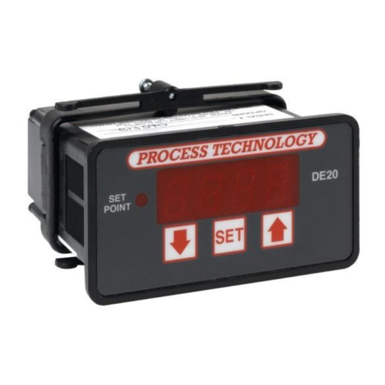
DE20 / T-DE20 Instruction Manual
Specifications .................................................................. 1
General Description ............................................................................ 2
Installation Procedure ......................................................................... 2
Overtemperature Protection .............................................................. 3
Set Point & Features ........................................................................... 4
Alarm Feature ...................................................................................... 4
Error Conditions ................................................................................... 4
Error Messages ................................................................................... 4
Power and Relay Wiring .................................................................... 5
Calibration ............................................................................................. 6
2 Wire RTD Sensor Calibration ........................................................ 6
Resistance Signal Calibration ........................................................... 7
3 Wire RTD Calibration ...................................................................... 7
Thermocouple Calibration ................................................................. 8
Voltage Signal Calibration .................................................................. 8
Current Input Calibration ................................................................. 10
Frequency Signal Calibration ......................................................... 10
USA/CN: 800-621-1998 • Fax: 440-974-9561 • www.processtechnology.com
TABLE OF CONTENTS
DE20 / T-DE20 Digital Temperature
7010 Lindsay Drive • Mentor, Ohio 44060 • Phone: 440-974-1300
Control
Configuration (Setup) ....................................................................... 11
Main Menu Summary...................................................................... 11
Sensor Type (U1) ............................................................................. 12
Signal Offset (U2) ............................................................................. 12
Signal Filter Setting (U4) .................................................................. 12
Set Point Dead Band (U5) .............................................................. 13
Display Stabilizer (U8) ...................................................................... 13
Set Point Limit (L) .............................................................................. 13
Heating or Cooling Switch (F2) ...................................................... 13
Alarm On/Off Switch (F3) ................................................................ 14
Unit Display Enable (F4) ................................................................. 14
Temperature Units Conversion (F5) ............................................. 14
Sensor DIP Switch Settings ........................................................... 14
Electrical Noise and Interference ................................................... 15
Installation in a Process Tank ......................................................... 15
COPYRIGHT 2016 Process Technology
Advertisement
Table of Contents

Summary of Contents for Process Technology T-DE20
-
Page 1: Table Of Contents
DE20 / T-DE20 Instruction Manual TABLE OF CONTENTS DE20 / T-DE20 Digital Temperature Control Specifications ..............1 Configuration (Setup) ............... 11 General Description ................2 Main Menu Summary..............11 Installation Procedure ................. 2 Sensor Type (U1) ................12 Overtemperature Protection .............. 3 Signal Offset (U2) ................ -
Page 2: Specifications
NIST Monograph 175, revision ITS-90 (Obsolete) Current 4-20mA DC Voltage (1-10 VDC) Frequency (0-200 Hz, counts/second), +/- 6 VDC p to p (up to 30VDC peak with Sw2 ON) Equipment protected throughout by Double Insulation or Reinforced Insulation. M-33-01-05-3/19/18 DE20/T-DE20 Manual... -
Page 3: General Description
Install a suitable liquid tight conduit fitting through the knockout opening following manufacturer’s instruc- tions and install field wiring. Using the wiring diagram M-33-01-05- 3/19/18 DE20/T-DE20 Manual... -
Page 4: Overtemperature Protection
Process Technology heaters include a thermal device (Protector 1, 2, or 3) on the heater to monitor the heat- er’s surface temperature. When wired properly, these... -
Page 5: Set Point & Features
Press the “SET” key to enter your new value. If you wish to accept the current value, press the “SET” key. The controller will automatically return to the operat- ing mode and display the current temperature. DE20/T-DE20 Manual M-33-01-05 - 3/19/18... -
Page 6: Power And Relay Wiring
Connect wires into their designated terminals and tighten the retaining screw which will secure the wire into place. M-33-01-05 3/19/18 DE20/T-DE20 Manual... -
Page 7: Calibration
Turn OFF all power. Step 1: Step 2: Remove rear cover. Step 3: Remove RTD sensor. Step 4: Install the precision resistors in place of the RTD sensor, as shown. M-33-01-05 3/19/18 DE20/T-DE20 Manual... -
Page 8: Resistance Signal Calibration
(i.e. 1000 ohms or 100 ohms), as shown. the RTD (i.e. 1000 ohms or 100 ohms). A suitable jumper cable to facilitate changing in- put resistance. A short piece of jumper wire (simulates third wire). M-33-01-05 3/19/18 DE20/T-DE20 Manual... -
Page 9: Thermocouple Calibration
(i.e. 511ºF or 266ºC). Step 12: Turn OFF power to the controller and *Input board 5417 is no longer available remove the precision resistors. Retain for future M-33-01-05 3/19/18 DE20/T-DE20 Manual... - Page 10 Make sure that the DIP switch settings are OFF, ON, rear cover of the control. Return the calibrated control OFF (see page 13). The voltage signal must be to service. con-nected across terminals #1 and #2 of the Adder Board DE20/T-DE20 Manual M-33-01-05 3/19/18...
-
Page 11: Current Input Calibration
400 ohm, 0.1% or better tolerance, to service. precision resistor. Frequency Signal (Pulse Train) The T-DE20 control measures frequency and com- pares that measurement with a “standard” set of val- ues derived from the microprocessor oscillator. Since Calibration procedures require the removal of this is a dedicated frequency, no field calibration is the rear cover of the control. -
Page 12: Configuration (Setup)
Toggle flag selects relay for direct vs. reverse acting Toggle flag to enable the “alarm set point” feature Alarm Enable Unit Display Enable Toggle flag enabling temperature units to be displayed Temperature Unit Toggle flag to select ºF or ºC M-33-01-05 3/19/18 DE20/T-DE20 Manual... -
Page 13: Sensor Type (U1)
When sensing frequency signal, this setting establishes the time period for the controller to wait for a pulse sig- nal. Use two (2) for this value when measuring frequency. This causes the control to measure frequencies as low as 1 hertz while updating the display once every two seconds. M-33-01-05 3/19/18 DE20/T-DE20 Manual... -
Page 14: Set Point Dead Band (U5)
When the setting is turned OFF (0), then the relay is reverse acting. That is, when a sensor reports a temperature less than the SET POINT, the relay is energized. At temperatures greater than the SET POINT, the relay is de-energized. This setting is common for heating applications. M-33-01-05 3/19/18 DE20/T-DE20 Manual... -
Page 15: Alarm On/Off Switch (F3)
DIP switch must also be configured. The DIP switch settings are as follows: Sensor DIP Switch: Selections Type 1000 ohm RTD 100 ohm RTD voltage current frequency (Illustration shows DIP switch setting for 100 ohm RTD.) M-33-01-05 3/19/18 DE20/T-DE20 Manual... -
Page 16: Electrical Noise And Interference
Electrical Noise and Interference Process Technology electronic controls are engineered, tested and manufactured to conform to Europe’s CE levels of electrical noise and interference found in typical industrial installations. It is always possible for electrical noise and interference to exceed the level of designed-in protection. This can happen, for example, if arc or spot-welding equipment is close to the control or if they share a common power line.
Need help?
Do you have a question about the T-DE20 and is the answer not in the manual?
Questions and answers