Table of Contents
Advertisement
Quick Links
Operating Instructions
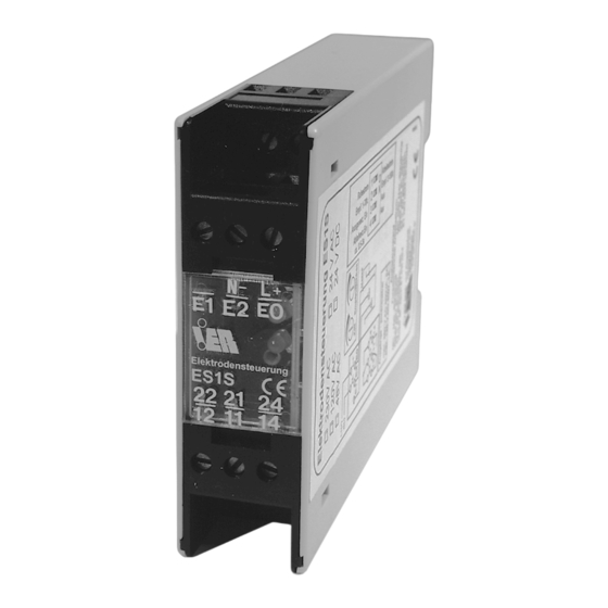
ES1S
Safety Precautions
•
The device may only be connected to supply voltage which is in
compliance with the technical data shown on the serial plate!
•
Installation, initial start-up and maintenance may only be
performed by trained personnel!
Technical Data
Power Supply
230 V AC, +/-10%, 50-60 Hz
Optional: 24, 115 V AC or 24 V DC +/-10%
See serial plate on device.
Power Consumption
approx. 2 VA
Ambient Temperature
-15 to +45°C
Housing
22.5 x 75 x 100 mm, IP40
Quick mount to standard rail
DIN EN 50 022 (35 x 7.5 mm top-hat rail)
or 88 x 150 x 130 mm, IP55 for surface mounting
Terminals
IP20, screw terminals
Conductor cross-section: max. 2.5 square mm
Measuring Circuit
Electrically isolated
Alternating voltage < 6V / < 2 mA
Cable Length
max. 300 m (for highly conductive liquids)
See figure 1.
min. conductor cross-section: 0.5 square mm, shielded
Measuring Functions
MIN-MAX control,
MIN control or MAX control
Sensitivity
Two adjustable ranges
1 to 70 kΩ / 5 to 150 kΩ
Can be selected / adjusted with DIP switch / potentiometer
(full left turn / anti clockwise = min. sensitivity)
Reset Hysteresis
approx. 20% of the selected sensitivity value
Relay Outputs
2 ea. floating changeover contacts
AC: max. 250 V, 5 A, 500 VA
DC: max. 125 V, 1 A, 40 W
SU0072e.DOC
03/03
Electrode Controls
© IER Eberhard Henkel GmbH
Operating Principle
Working current / closed-circuit current
selectable with DIP switch
Delay
ON delay / OFF delay: 0.5 to 3 sec.
adjustable with potentiometer (full left = approx. 0,5 sec.)
1 ea. "on" LED, 1 ea. switching status LED
CE Mark of Approval
In accordance with low-voltage directive (73/23/EWG),
EMC directive (89/336/EWG) and
•
EN 50 082-2:1995
•
EN 55 011 (Class A): 1991
•
EN 61010-1: 1993
Applications Limits
Conductive liquid-level controls are not suited for liquids which
contain oil or grease, or which may cause electrically insulating
deposits at the electrodes.
Functional Description
ES1S electrode controls function in accordance with the
conductive principle, i.e. the electrical conductivity of the liquid to
be monitored is used to establish an electrical connection between
the immersed electrodes.
Measuring Ranges
ES1S electrode controls can be used for liquids with a resistance
between the electrodes of less than 150 kΩ (observe maximum
cable length!).
Controls
Intermittent switching (minimum / maximum liquid level) with three
electrodes
Monitoring of a specific fill level (overflow / empty alarm) with two
electrodes. A metal container can be used as the reference
electrode.
Electrical Connections
Power Supply
L1 N
+
-
12
L+ N-
11
1
14
ON
22
OFF
21
24
E0 E1 E2
Filling pump relay/contactor pulls
in when MIN electrode is exposed,
MAX Electrode
... and is released when
MAX electrode is immersed.
MIN Electrode
Ref. Electrode
Wiring Diagram 1: Filling the Container
Power Supply
L1 N
+
-
12
L+ N-
11
1
14
ON
22
OFF
21
24
E0 E1 E2
Discharge pump relay/contactor pulls
in when MAX electrode is immersed,
... and is released when
MAX Electrode
MIN electrode is exposed.
MIN Electrode
Ref. Electrode
Wiring Diagram 2: Draining the Container
Control Voltage
Filling Pump
K
Relay / Contactor
Control Voltage
Discharge Pump
K
Relay / Contactor
Subject to change without notice
Advertisement
Table of Contents

Summary of Contents for Ier ES1S
-
Page 1: Technical Data
• Measuring Ranges The device may only be connected to supply voltage which is in ES1S electrode controls can be used for liquids with a resistance compliance with the technical data shown on the serial plate! • Installation, initial start-up and maintenance may only be between the electrodes of less than 150 kΩ... - Page 2 Full Left Full Right Tel. +49 (0)621 84224-0 Fax: +49 (0)621 84224-90 P1: Sensitivity min. max. e-Mail: info@IER.de Internet: www.IER.de P2: Delay approx. 0.5 sec approx. 3 sec SU0072e.DOC 03/03 © IER Eberhard Henkel GmbH Subject to change without notice...
Need help?
Do you have a question about the ES1S and is the answer not in the manual?
Questions and answers