Table of Contents
Advertisement
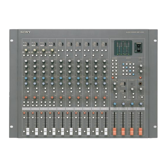
AUDIO MIXER
SRP-V200
Operating instructions
Before operating the unit, please read this manual and the supplied "WARNING"
thoroughly and retain it for future reference.
Precautions
On safety (Refer to the supplied "WARNING".)
• Should any liquid or solid object fall into the cabinet, unplug the unit and
have it checked by qualified personnel before operating it any further.
• Unplug the unit from the wall outlet if it is not to be used for an extended
period of time. To disconnect the cord, pull it out by grasping the plug.
Never pull the cord itself.
On installation
• Do not install the unit in a location near heat sources such as radiators or
air ducts, or in a place subject to direct sunlight, excessive dust, mechanical
vibration or shock.
On operation
• Before making program source connections, be sure to turn the power
switch off and unplug the unit.
• When the unit is not used, turn the power off to conserve energy and to
extend the useful life of your unit.
On cleaning the cabinet
Clean the cabinet, panel and controls with a soft cloth lightly moistened with
mild detergent solution. Do not use any type of abrasive pad, scouring powder
or solvent such as alcohol or benzine.
On repacking
Do not throw away the carton and the packing material. It makes an ideal
container for transporting the unit.
When shipping the unit for repair work or to another location, repack it as it
was.
If you have any questions or problems concerning your unit, please contact
your nearest Sony dealer.
Warning
Notice for the Customers in the United Kingdom
IMPORTANT
The wires in this mains lead are coloured in accordance with the
following code:
Blue
:
Neutral
Brown
:
Live
As the colours of the wires in the mains lead of this apparatus may
not correspond with the coloured markings identifying the terminals
in your plug, proceed as follows:
The wire which is coloured blue must be connected to the terminal
which is marked with the letter N or coloured black. The wire which
is coloured brown must be connected to the terminal which is
marked with the letter L or coloured red. Do not connect either wire
to the earth terminal in the plug which is marked by the letter E or
by the safety earth symbol Y or coloured green or green-and-yellow.
©1999 by Sony Sound Tec Corporation
Table of Contents
Warning .............................................
Main characteristics .........................
Dimensions .......................................
MONO INPUT section .........................
STEREO INPUT section .....................
MONITOR section ...............................
MASTER section ................................
INTERFACE section ...........................
BACK PANEL ......................................
System Configuration ......................
Video Editor Connection .................
Block diagram...................................
Main specifications ..........................
2-346-938-11 (2)
2
3
3
4
4
6
8
10
11
12
14
18
24
25
1
Advertisement
Table of Contents

Related Manuals for Sony SRP-V200


Summary of Contents for Sony SRP-V200
-
Page 1: Table Of Contents
L or coloured red. Do not connect either wire to the earth terminal in the plug which is marked by the letter E or by the safety earth symbol Y or coloured green or green-and-yellow. ©1999 by Sony Sound Tec Corporation... -
Page 2: Warning
WARNING English Svenska WARNING VARNING To prevent fire or shock hazard, do not expose the unit Utsätt inte apparaten för regn och fukt för att undvika top rain or moisture. riskerna för brand och/eller elektriska stötar. Öppna inte höljet. Det kan resultera i risk för elektriska To avoid electrical shock, do not open the cabinet. -
Page 3: Main Characteristics
Main characteristics The SRP-V200 is a compact audio mixer designed for use in a small or medium-size video edit suite. Mounted in a 19" rack and controlled from the video editor, the SRP-V200 enables audio editing in synchronization with video images. -
Page 4: Name And Function Of Each Parts
Name and function of each parts MONO INPUT section MIC/+48V LINE LEVEL HIGH PEAK -∞ -∞ EVEN MUTING LOCAL ∞... -
Page 5: High
Input-A Level Switch PRE (Pre-Fader) Button Controls the signal level at the mono input connector A. Used to assign either pre-fader or post-fader signal to the The three switch positions can be used as follows according AUX outputs. The pre-fader signal is the signal before to the connected source unit. -
Page 6: Stereo Input Section
Name and function of each parts STEREO INPUT section -10dBu +4dBu 600Ω +4dBu HIGH PEAK EVEN -∞ EVEN MUTING LOCAL ∞... - Page 7 Input Level Switch AUX LVL (AUX Output Level) Control Allows adjustment of the signal level at the STEREO Controls the level of the signal to be sent to the AUX INPUT connector according to the input source unit. outputs. The reference level can be obtained by setting the +4dBu: control to the "0"...
-
Page 8: Monitor Section
Name and function of each parts MONITOR section POWER -∞ MONITOR SOURCE EDITOR AUX 1 AUX 2 OUTPUT OUTPUT AUX 3 AUX 4 RETURN -∞ MONI 1-2 MONI 3-4 -∞ EDIT MUTING RETURN REC MODE TALKBACK PHONES FIX 2CH FIX 4CH FREE 2CH FREE 4CH EVEN... - Page 9 Power Switch MONITOR OUTPUT 1-2/3-4 Controls Turns on the power when set to the "I" position. Each provides control over the output level from the MONITOR OUTPUT connectors 1 and 2 or 3 and 4. The Level Meters maximum position ("0" position) is the reference level. With the use of the METER switch, these meters can be MUTING Button switched to show either MASTER or MONITOR output...
-
Page 10: Master Section
Name and function of each parts MONITOR section OSCILLATOR Switch TB OUT (Talkback Output) Switch Pressing this switch supplies a reference-level oscillator The signal from the built-in microphone is output from the signal (1kHz, +4dBu, sine-wave test signal) to MASTER TB output connector. -
Page 11: Interface Section
A1/A2 STEREO INPUT MONO INPUT 600Ω The SRP-V200 uses parallel interfaces for connection to the video editor. A1/A2 and A3/A4 Connectors When the FREE 2CH or FREE 4CH mode is selected, these connectors are used to connect the A/B/C/D signals for controlling the preview or review monitor signals. -
Page 12: Back Panel
Name and function of each parts BACK PANEL 10 11 12 13 MASTER OUTPUT MONITOR OUTPUT RTN IN AUX OUTPUT A3/A4 TB OUT STEREO IN VOLTAGE MONITOR SELECTOR 230V 120V 600Ω MASTER MONO INPUT-A Connectors STEREO INPUT Connectors XLR-3-31 type XLR-3-31 type Balanced(Pin 1: ground, Pin 2: hot, Pin 3: cold) Balanced(Pin 1: ground, Pin 2: hot, Pin 3: cold) -
Page 13: Local
EDITOR REMOTE A1/A2 INPUT MONO INPUT 600Ω VOLTAGE Selector TB OUT (Talkback Output) Connector Before making AC connection, set this selector to the Phono jack position of your local power line voltage. If the plug of the Unbalanced AC cord does not fit the wall outlet, use the supplied plug Reference level: -5 dBu adapter. -
Page 14: System Configuration
System Configurations The SRP-V200 can be adapted to different video systems by setting the REC MODE switch according to the number of VTRs used in the system as well as the number of audio channels offered by each VTR. Editing System Using 2-channel VTR (Fixed Recorder Assignment) Set the REC MODE switch to the FIX 2CH position. - Page 15 Editing System Using 4-channel VTR (Fixed Recorder Assignment) Press the B buttons on all mono input channels 1 through 4 and set the REC MODE switch to the FIX 4CH position. The 600Ω switches for MONO INPUT B and MONITOR INPUT connectors, as well as the LEVEL controls for stereo input signals (ST1 to 6), must be set according to the connected VTR.
- Page 16 System Configurations Editing System Using 2-channel VTR (Free Recorder Assignment) Set the REC MODE switch to the FREE 2CH position. Which VTR to use as the recorder is determined by the settings on the video editor. The LEVEL controls for stereo input signals (ST3 to 6) must be set according to the connected VTR.
- Page 17 Editing System Using 4-channel VTR (Free Recorder Assignment) Press the B buttons on all mono input channels 1 through 4 and set the REC MODE switch to the FREE 4CH position. Which VTR to use as the recorder depends on the settings on the video editor.
-
Page 18: Video Editor Connection
• For connections, refer to Editing System Using 2-channel VTR (Fixed Recorder Assignment). • Set the REC MODE switch of the SRP-V200 to FIX 2CH. Also set the mixer remote control mode selector of the PVE-500 to PARALLEL. • The table below shows the relationship between the source selector buttons (P1, P2, AUX 1 and AUX 2) of the PVE-500 and the input channels of the SRP-V200. - Page 19 • For connections, refer to Editing System Using 2-channel VTR (Free Recorder Assignment) or Editing System Using 4-channel VTR (Free Recorder Assignment). • Set the REC MODE switch of the SRP-V200 to FREE 2CH or FREE 4CH according to the number of audio channels of the VTR.
- Page 20 • Tabulated below is the relationship between the mixer cross points (MIXER XPT) and audio monitor switcher cross points (MON-A) of the BVE-2000 and the input/output channels of the SRP-V200. Note: In the FREE 4CH mode, it is impossible to monitor the audio channel 3/4 signals by remote controlling the mixer from the BVE-2000.
- Page 21 VCA Connector Function H: TTL high level L: TTL low level A1/A2, A3/A4 Connector Pin Assignment A1-A/B/C/D Connector Function The following signals can be sent to MONITOR matrix input 1 by turning on the EDIT button on the editor.
- Page 22 Video Editor Connection A2-A/B/C/D Connector Function The following signals can be sent to MONITOR matrix input 2 by turning on the EDIT button on the editor. A3-A/B/C/D Connector Function The following signals can be sent to MONITOR matrix input 3 by turning on the EDIT button on the editor.
- Page 23 Remote connector REMOTE Connector Pin Assignment Remote Connector Specifications VCA control input Input voltage: DC +5 to 0 V Audio signal level adjustment: Approx. -20 dB/V Input impedance: More than 10kΩ Fader start output Circuit: Open collector output Max. voltage: 30 V Max.
-
Page 24: Block Diagram
Block diagram MASTER 1-4 AUX 1-4 PREVIEW 1-4 MASTER CONTROL OUTPUT MASTER 1 INPUT A MIC +48V LINE MASTER 2 LEVEL AUX1/3 LOW MID HIGH INPUT B (+4dBu) MASTER 3 AUX2/4 PEAK MASTER 4 PREVIEW MUTING FADER AUX MASTER 1 AUX OUTPUT LOCAL MONO INPUT 1-4... -
Page 25: Main Specifications
Channel fader:0dB) Crosstalk Master output to Master output: Less than -80dB (10kHz,except stereo L/R) (0dBu=0.775V) Interface section Editor interface Sony standred parallel type protocol Connector type: A1/A2 connector 25-pin D-sub female type A3/A4 connector 25-pin D-sub female type VCA connector... - Page 26 Made in Japan...
Need help?
Do you have a question about the SRP-V200 and is the answer not in the manual?
Questions and answers