Table of Contents
Advertisement
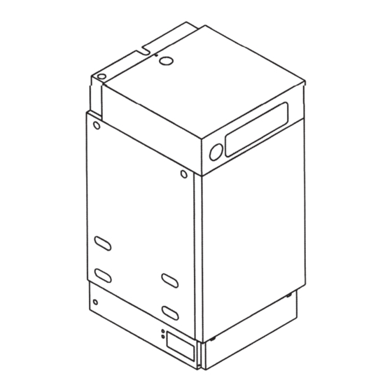
TRANSIT SCREW
MAIN POWER SUPPLY
CABLE ENTRY
LIFTING AND PLUMBING
ACCESS EACH SIDE
EXTERNAL CONTROLS
(AND IMMERSION
HEATER CABLE ENTRY)
PLUMBING ACCESS
EACH SIDE
140
The code of practice for the installation, commissioning
& servicing of central heating systems
BAXI POTTERTON
BROWNEDGE ROAD
BAMBER BRIDGE
PRESTON PR5 6SN
(Technical Helpline) TEL 0870 606 0955
(Service) TEL 0870 606 0933 FAX 0870 606 0966
(Spares) TEL 0870 6060454
"Powermax" is a trademark of Baxi Group Ltd
Publication No. P443 - 12/05
AUTO VENT ACCESS
TOP PANEL
FRONT PANEL
(2 SCREWS)
PLINTH
(4 SCREWS)
(2 SCREWS)
Guide to Panel Removal
Guide to panel removal
Auto vent access
Top panel
Main power supply
cable entry
External controls
cable entry
Lifting and plumbing
access each side
155x x
Upper front panel and
retaining screw
Lower front panel
(2 screws)
Plinth (4 screws)
Advertisement
Table of Contents


Need help?
Do you have a question about the OV 140 P Series and is the answer not in the manual?
Questions and answers
What should the pressure show on the boiler pressure guage
The recommended pressure reading on the PowerMax OV 140 P Series boiler is approximately 3.8 to 4.4 mbar for the 140 model. For the 155x model, the recommended range is 4.8 to 5.5 mbar.
This answer is automatically generated