
Summary of Contents for Chiltrix CXI34
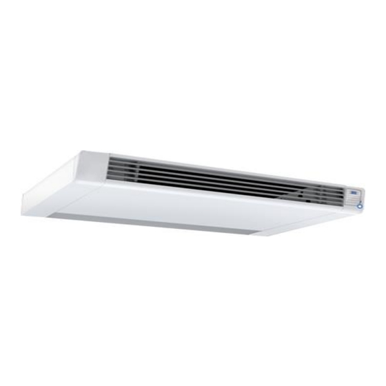
- Page 1 Chiltrix 5.1” Thin DC - Inverter Water Fan Coil Unit Floor, Wall or Ceiling Universal Mount Manual Version 1.4...
-
Page 2: Table Of Contents
CONTENTS CHAPTER 1 GENERAL INTRODUCTION..........................3 Preface.................................. 3 Product Introduction ............................3 Measurements ..............................3 Product Features ..............................5 Safety Precautions and Warnings.........................5 CHAPTER 2 PERFORMANCE AND SPECIFICATIONS.......................7 Performance Curves ............................7 Water Flow Rates and Water Pressure Drops ....................17 CHAPTER 3 INSTALLATION..............................18 Installation Precaution ............................ -
Page 3: Chapter 1 General Introduction
Chiltrix reserves the right to change the specification and design of units which may lead to content change. Always use the latest version of this manual, the version number is listed on the front page. - Page 4 Accessories The following assemblies are included in the box. Vertical Fan Coil Installation Template Drain Pipe Brackets Toggle Bolts Screws Screw Caps Remote Controller Inspecting and Handling the Unit After delivery, the package should be checked and any damage should be reported immediately to the carrier claims agent.
-
Page 5: Product Features
4. Product Features Extremely compact structure, attractive cabinet, and easy to transport. It can control the temperature both in summer and winter. Uses a DC fan motor combined with new air-guide technology makes for low noise operation. Our air exchanger (fin-coil) has a hydrophilic coating. - Page 6 INSTALLATION Meaning Make sure the base or pad of the heat pump is strong enough to avoid the unit tipping over. Be sure to use a dedicated circuit breaker, failure to do so may lead to electrical shock or fire. Need circuit breaker Meaning OPERATION...
-
Page 7: Chapter 2 Performance And Specifications
CHAPTER 2 PERFORMANCE AND SPECIFICATION CXI-34 Performance curve (at 2.4GPM per each 12,000BTU) Temps in F Heating capacity performance data and curve Entering Performance curve 8000 water 7000 6000 Indoor air 5000 4000 2802 3556 4309 5062 6205 7348 3000 2626 3375 4124... - Page 8 CXI-34 The leaving water temperature data – Heating Performance curve Entering water Indoor air 87.0 93.9 100.8 107.6 113.4 119.1 87.5 94.4 101.3 108.1 113.8 119.5 88.1 94.9 101.8 108.6 114.3 120.1 62.6 64.4 66.2 69.8 71.6 73.4 75.2 88.6 95.4 102.3 109.2...
- Page 9 CXI-65 Performance curve (at 2.4GPM per each 12,000BTU) Temps in F Heating capacity performance data and curve Performance curve Entering 13000 water 11000 9000 Indoor air 5270 6687 8103 9520 10535 11550 7000 4939 6347 7755 9163 10252 11340 5000 11025 4590 6007...
- Page 10 CXI-65 The leaving water temperature data – Heating Performance curve Entering water Indoor air 87.3 94.2 101.1 108.0 115.5 123.0 87.7 94.7 101.6 108.5 115.9 123.3 88.3 95.2 102.1 109.0 116.4 123.8 88.8 95.7 102.6 109.5 116.9 124.3 62.6 64.4 66.2 69.8 71.6...
- Page 11 CXI-85 Performance curve (at 2.4GPM per each 12,000BTU) temps in F Heating capacity performance data and curve Performance curve Entering 17000 water 15000 13000 Indoor air 11000 16830 7068 8968 10868 12768 14799 9000 16524 6623 8512 10401 12289 14407 7000 5000 16065...
- Page 12 CXI-85 The leaving water temperature data – Heating Performance curve Entering water Indoor air 87.2 94.0 100.9 107.8 114.6 121.3 87.6 94.5 101.5 108.4 115.0 121.7 62.6 64.4 66.2 69.8 71.6 73.4 75.2 88.2 95.1 101.9 108.8 115.5 122.2 Indoor air temperature (℉) 88.7 95.6 102.5...
- Page 13 CXI-120 Performance curve (at 2.4GPM per each 12,000BTU) Temps in F Heating capacity performance data and curve Performance curve 25000 Entering water 23000 21000 19000 17000 15000 13000 11000 Indoor air 9000 7000 21692 9052 11485 13919 16352 19022 5000 62.6 64.4 66.2...
- Page 14 CXI-120 The leaving water temperature data – Heating Performance curve Entering water Indoor 87.9 95.0 102.1 109.2 116.1 123.0 88.3 95.4 102.5 109.6 116.5 123.3 62.6 64.4 66.2 69.8 71.6 73.4 75.2 88.8 95.9 103.0 110.1 116.9 123.7 Indoor air temperature (℉) Entering water 95℉...
- Page 15 CXI-148 Performance curve (at 2.4GPM per each 12,000BTU) Temps in F Heating capacity performance data and curve Entering Performance curve water 35000 30000 Indoor air 25000 11036 14003 16969 19936 23993 28050 20000 10342 13291 16240 19188 23364 27540 15000 10000 9612 12579...
- Page 16 CXI-148 The leaving water temperature data – Heating Performance curve Entering Water Indoor air 87.9 95.0 102.1 109.2 115.6 122.0 88.4 95.5 102.6 109.7 116.0 122.3 88.8 95.9 103.0 110.1 116.5 122.8 89.3 96.4 103.5 110.6 117.0 123.3 62.6 64.4 66.2 69.8 71.6...
-
Page 17: Water Flow Rates And Water Pressure Drops
Please note; The chart above refers to GPM per Fan Coil and not GPM per CX30... -
Page 18: Chapter 3 Installation
Not following the instructions can cause the unit to malfunction and also invalidate the warranty. Chiltrix will not be responsible for any damage to persons, animals or property caused by improper installation or operation. -
Page 19: Removing The Side Covers
3. Removing the side covers With the fan coil lying face down on the box, locate the rubber plug on the outside cover and remove the screw behind it. Gently tap the bottom of the side cover and remove the cover. Do the same for the right side. -
Page 20: Wall Or Vertical Floor Mount Installation
4. Wall Installation or Vertical Floor Mount Using the paper template, trace the position of the wall (fig.10). Drill the holes and insert the anchor bolts (2 for each bracket) (fig.11 ref. A); attach the bracket (fig.11 ref. B) included with the FCU. - Page 21 Do not over-tighten the screws so that the brackets can be adjusted with a spirit level (fig. 15). Then fully tighten the four screws to block the two brackets. Mount the unit, checking that it fits correctly onto the brackets and that it is stable Fig 16. (fig.
-
Page 22: Hydronic Installation
5. Hydronic Connections installation& wall installation. loor To connect the inlet and outlet water pipes, refer to the figures below. -
Page 23: Condensate Discharge
6. Condensate discharge, floor or wall mount only. The condensate discharge network must be properly sized, (minimum pipe diameter 5/8” OD) and the piping must be positioned in such a way as to keep an inclination, of at least 1%. The drain pipe is connected to the pan, positioned under the heat exchanger coil (drain 1). -
Page 24: Ceiling Installation
7. Ceiling Installation 7.1 Minimum installation distances-------horizontal Ceiling installation Figure 24 indicates the minimum mounting distances between the wall-mounted Fan Coil and furniture present in the room. To remove the side opening refer to page 19 for detailed instructions. Dismount the upper grill (fig.25 ref. A) by unscrewing the attaching screws. Remove the rubber plug (fig. - Page 25 7.2 Ceiling Mounting Adjust the units installation angle so that the unit is level and ensure the condensation drain- pipe is connected to the 5/8” OD port for condensation water draining when mounted on the ceiling (fig. 27). Mount the unit, checking that it fits correctly on the brackets and it is stable (fig. 28 and 27).
-
Page 26: Hydroic Connections For Horizontal Installations
8. Hydronic connections horizontal installation 8.1 Refer to fig. 29 and fig. 30 to connect the inlet and outlet lines. Fig. 29 Fig. 30 Inlet and outlet water lines are ¾” NPT. -
Page 27: Maintenance
9. Maintenance Cleaning the Filter To keep the unit problem free, it is suggested to maintain and clean the unit every six months. Please take the following steps to clean the strainer regularly: 1) Remove the plastic tape which is used to secure the air inlet grill during shipping. (A Fig.33) 2) Next, lift the grill upward about ¼”... - Page 28 5) Set the filter net and the air return grille to the original place. (Fig.39)。 6)Clean up the units outer cover with a soft damp rag (Fig. 40). To protect the paint, use a mild detergent. Warning: Cut off power supply before cleaning or maintaining the unit.
-
Page 29: Chapter 4 Front Panel Operation
CHAPTER 4 Front Panel Operation Press this button and select the mode you want to set. Cooling mode: Cooling indicator light keeps on (green) Heating mode: Heating indicator light keeps on (red) Automatic mode: Cooling indicator light and heating indicator light flashes in turn. Ventilating mode: Cooling and heating indicator lights are off, the fan indicator light keeps on according to the chosen fan speed. - Page 30 You could check the setting temperature of unit by pressing this button once. You could increase the setting temperature by pressing this button again. You could check the setting temperature of unit by pressing this button once. You could increase the setting temperature by pressing this button again. 2.
- Page 32 Notes: 1) The operation of all parameter settings is the same. 2) If you press the on/off button when the controller is showing the parameter value, it will switch back to the main interface without saving the setting. 3) If there is no operation in 20 seconds, system would remember the setting and switch back to the main interface.
-
Page 33: Parameters
3. Parameters Fan coil parameter list for MD1001 controller (V2.0) Meaning Range Default Level Target temp upper limit, Maximum Temperature, user setting 60°F ~ 205°F 86°F Factory Target temp lower limit, Minimum Temperature, user setting 60°F ~ 205°F 46°F Factory Target temp in cooling mode. -
Page 34: Remote Control
4. REMOTE CONTROL Note: 1) The key “SET” and “OK” are disabled. 2) Take out the batteries if you do not use the remote controller for a long time. 3) Take out the batteries for 35 minutes to reset the remote controller. - Page 35 Using the remote controller Function of “F.Cool” and “F.Heat” By pressing the key “F.Cool”, the system will be automatically set to the cooling mode With a high fan speed. By pressing the key“F.Heat”, the system will be automatically set to the heating mode with a high fan speed.
-
Page 36: Wiring Diagram
5. Wiring Diagram Signal meaning DC Fan Motor TEMP Sensors To ambient and coil temperature OUT1 To electromagnetic valve Hot wire 120 vac Power in Neutral wire Power in... -
Page 37: Standard Fan Coil Loop Pump Wiring
6. Standard Fan Coil Loop Pump Wiring Typical control circuit for adding a second pump to a fan coil Loop using SPST 24vac coil relays. Relays must have the proper contact load rating for the selected pump. -
Page 38: Sensor Resistance Table
7. Resistance Chart T(⁰F) R(KΩ) T(⁰F) R(KΩ) T(⁰F) R(KΩ) -22.0 63.7306 57.2 7.7643 136.4 1.5636 -20.2 60.3223 59.0 7.4506 138.2 1.5142 -18.4 57.1180 60.8 7.1513 140.0 1.4666 -16.6 54.1043 62.6 6.8658 141.8 1.4206 -14.8 51.2386 64.4 6.5934 143.6 1.3763 -13.0 48.5994 66.2 6.3333... -
Page 39: Troubleshooting
1) When there is a sensor error code, measure the resistance value of the sensor with a multimeter, and compare the ambient temperature with the table above, then you will know whether the NTC resistance sensor is faulty. 2) Generally, from above table, you can know the temperature by testing NTC resistance value. 8. -
Page 40: Parts Breakdown
9. Exploded Views Chiltrix CXI34... - Page 41 Chiltrix CXI34 Part Code Part Name Note Part Code Part No. Note 30036-220030 Left wind shield 30036-210014 Fan motor bracket 30036-210011 Left support 20000-340073 Electric cable 30036-220009 Left dam plate condenser 20000-330086 DC fan motor 30034-220001 Water pan 30036-210015 Fixed plate...
- Page 42 Chiltrix CXI65...
- Page 43 Chiltrix CXI65 Part Code Part Name Note Part Code Part No. Note 30036-220030 Left wind shield 30036-210014 Fan motor bracket 30036-210011 Left support 20000-340073 Electric cable 30036-220009 Left dam plate condenser 20000-330086 DC fan motor 30034-220001 Water pan 30036-210015 Fixed plate...
- Page 44 Chiltrix CXI85...
- Page 45 Chiltrix CXI85 Part Code Part Name Note Part Code Part No. Note 30036-220030 Left wind shield 30036-210014 Fan motor bracket 30036-210011 Left support 20000-340073 Electric cable 30036-220009 Left dam plate condenser 20000-330086 DC fan motor 30034-220001 Water pan 30036-210015 Fixed plate...
- Page 46 Chiltrix CXI120...
- Page 47 Chiltrix CXI120 Part Code Part Name Note Part Code Part No. Note 30036-220030 Left wind shield 30036-210014 Fan motor bracket 30036-210011 Left support 20000-340073 Electric cable 30036-220009 Left dam plate condenser 20000-330086 DC fan motor 30034-220001 Water pan 30036-210015 Fixed plate...
- Page 48 Chiltrix CXI148...
- Page 49 Chiltrix CXI148 Part Code Part Name Part Code Part Name 3124-210012 Front Panel 31022-220012 Electrical box lining panel 31024-210002 Air inlet grill 20000-430061 LED102 Filter net 31022-220011 Right top cover 3100-220022/23 31022- Holder for wind Switch button 31022-220015/16 210048/14 deflector...
- Page 50 --------...
Need help?
Do you have a question about the CXI34 and is the answer not in the manual?
Questions and answers