Table of Contents
Advertisement
Quick Links
Advertisement
Table of Contents

Summary of Contents for Cattron Safe-E-Stop
- Page 1 ™ SAFE-E-STOP Personal Safety System User Guide 9M02-8978-A001-EN...
-
Page 2: Communication Loss Recovery Stage
Cattron Holdings, Inc., or any of its affiliates or agents shall not be liable for incidental or consequential damages of any kind. All Cattron products are sold pursuant to the Terms and Conditions of Sale, a copy of which will be furnished upon request. When used as a tradename herein, Cattron means Cattron Holdings, Inc. -
Page 3: Table Of Contents
Safe-E-Stop™ User Guide Contents 1. Introduction Terminology Warnings and Cautions MSD wiring Verification of correct device Verification of correct linking Placement of PSD in charger No serviceable parts Regulatory Compliance Awareness of PSD range and Hazards around the machine The system may cause an unexpected stop of the machine The safety analysis shall consider the reaction time of the system 2.10... - Page 4 Safe-E-Stop™ User Guide MSD Configuration 2.19 Configuration Part Number PSD Configuration MSD Configuration PSD Overview PSD Status Indications 6.2.1 PSD LEDs 6.2.1.1 PSD LCD 6.2.1.2 Radio signal level Monitoring 6.2.1.3 Battery Monitoring 6.2.1.4 General Status Monitoring Joining an E-Stop Group Normal Operation 6.4.1...
- Page 5 Safe-E-Stop™ User Guide MSD Status Indicators MSD LEDs MSD LCD MSD Operational States MSD Information and Setup MSD Ethernet Address Configuration 8.6.1 Ethernet Telegram Content MSD Operation MSD Installation 8.8.1 Safety Instructions for Installation 8.8.2 MSD Installation Notes on Enclosure 8.8.2.1...
- Page 6 Safe-E-Stop™ User Guide Band F (902-927MHz) Band F Channel Spacing Rules Band J (929MHz) Band J Channel Spacing Rules Appendix C: Approvals and Compliance Notifications FCC Caution EU Caution Equipment Rating Declaration of Conformity Appendix D: Ethernet Configuration & Data Mapping...
- Page 7 Safe-E-Stop™ User Guide Appendix H: Safety Manual for Safe-E-Stop Functions Failure Modes Operational Constraints Appendix I: Safety Performance Level Version 17...
-
Page 8: Introduction
Safe-E-Stop™ User Guide 1. Introduction This manual provides guidance to installers and users of the Cattron Safe-E-Stop Personal Safety System. Terminology The following represent important acronyms and long form used in this document: Personal Safety Device (the unit worn by a machine operator) -
Page 9: Warnings And Cautions
Safe-E-Stop™ User Guide Warnings and Cautions WARNING and CAUTION statements are strategically placed throughout all text prior to operating or maintenance procedures, practices, or conditions considered essential to the protection of personnel or equipment and property. Before starting any task, review and understand the WARNINGS or CAUTIONS included in the text. -
Page 10: No Serviceable Parts
2.5 No serviceable parts WARNING There are no user serviceable parts in this PSD / MSD system; please return damaged units to Cattron or a Cattron authorized service center for service and do not attempt to repair these units. Unauthorized repairs will void the unit’s safety rating and could compromise the unit’s ability to stop your machine, which in turn could result in loss of ability to stop an impending emergency situation and may lead to injury or death. -
Page 11: The System May Cause An Unexpected Stop Of The Machine
2.11 Frequency Change WARNING Selection of the correct operating frequency is entirely the responsibility of the user and Cattron accepts no responsibility for incorrect frequency selection and configuration. The frequency selected must strictly conform to channel setting rules shown in section 4 of this manual or the system may not function correctly. -
Page 12: Intended Use
▪ Product modifications may not be carried out. ▪ Only original spare units from Cattron must be used. ▪ Periodical inspections either required by law or prescribed in this user manual shall be carried out within the prescribed intervals. -
Page 13: Equipment Rating Warning
Safe-E-Stop™ User Guide 2.16 Equipment rating warning CAUTION Damage of the device The PSD is rated at IP67 and an operating temperature range of -20°C to +60°C; do not use the PSD for conditions beyond these limits. The PSD battery cannot be charged if its temperature exceeds 40°C. -
Page 14: Operating Principle
Safe-E-Stop™ User Guide Operating Principle 3.1 General The MSD has two safety relays that are wired in series with an external hard-wired E-Stop circuit that provides a machine with the ability to run. The MSD safety relays are changeover types that are held energized in normal (non-e-stop/run) operation. -
Page 15: Telegram Security
Safe-E-Stop™ User Guide 3.3 Telegram Security The transmitted telegram contains several security features. 3.3.1 System Address Your Personal Safety System uses 32,768 unique Master Addresses, and 15 Sub Addresses per MSD (one per each possible associated PSD). This system address is contained in every telegram sent between the MSD and PSD. The data is considered valid only when the address combination matches. -
Page 16: Frequency Selection
If any other systems (including other Safe-E-Stop systems) are operating within 10m of the location that the Safe-E-Stop will be used, then a frequency that is at least as far away as is shown in the ‘CH SPACING Separation’ column should be chosen. -
Page 17: Site Planning
Safe-E-Stop™ User Guide Table 2: Frequencies That Are Not Supported VOID REQUENCIES Band B Band D Band F 434,177,500 466,937,500 902,600,000 912,100,000 921,600,000 902,700,000 912,200,000 921,700,000 902,800,000 912,300,000 921,800,000 902,900,000 921,100,000 921,900,000 911,700,000 921,200,000 922,000,000 911,800,000 921,300,000 922,100,000 911,900,000 921,400,000... -
Page 18: Psd And Msd Configuration Parameters
The PSD will show the frequency configuration on the LCD when first turned on. As an additional aid to visual identification and differentiation, the following is available as an option: ▪ A sheet of labels of various colors of Cattron logo as a user installation item. Version 17... -
Page 19: Msd Configuration
Safe-E-Stop™ User Guide 5.2 MSD Configuration Your MSD has been manufactured to operate in a specific RF band and is fitted with a specific Ethernet option. Within that band all users can configure the specific RF channel. ● Authorized users can set the System master address. -
Page 20: Configuration Part Number
Safe-E-Stop™ User Guide Table 4: Frequency Bands BAND FREQ MHZ TYPICALLY USED IN China EU & Other EU Licensed NA and Other Licensed Japan 2.19 Configuration Part Number PSD Configuration PSD-2-X-Y Where 2 is the current version Where X is the RF Band... -
Page 21: Psd
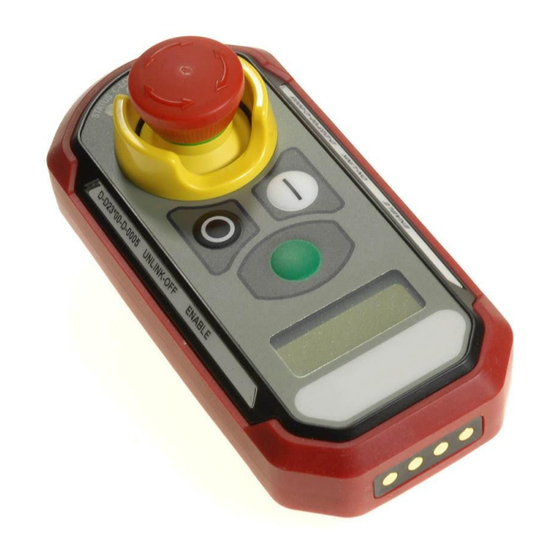
Safe-E-Stop™ User Guide 6.1 PSD Overview PSDs can be considered a set of wireless E-Stop switches that are dynamically linked to the MSD on an as- needed basis. The MSD does not need a PSD to be connected in order to keep its E-Stop Safety Relays closed;... -
Page 22: Psd Leds
Safe-E-Stop™ User Guide 6.2.1 PSD LEDs Referring to above, there are four LEDs above the E-Stop switch. These are: Figure 3 This will be flashing: GREEN: Normal operation STATUS ORANGE: Conditions that require the user to be aware RED: Conditions that require the user to take corrective action... -
Page 23: General Status Monitoring
Safe-E-Stop™ User Guide Figure 5: Battery Level Monitoring 6.2.1.4 General Status Monitoring The main LCD area gives general status as defined in the tables below. 6.3 Joining an E-Stop Group For a PSD to link to a group: Verify that the PSD has the correct configuration for the MSD to be joined. - Page 24 Safe-E-Stop™ User Guide Flashing 3 short MSD NOT MSD not seen Orange pulses SEEN When ready to join the group, ensure that you are in the work area and press and hold the ‘|’ button for longer than half a second. Monitor the PSD display for information on linking status. The PSD returns a status message depending on several factors as displayed in the following table.
- Page 25 Safe-E-Stop™ User Guide Once a PSD has joined and become an active member of the E-Stop group, the PSD displays its current status as indicated in the following table, where # is the current ID of this or another PSD:...
-
Page 26: Normal Operation
Safe-E-Stop™ User Guide The Status LED generally has the following meaning: Table 9: PSD Status LED General Meaning Normal operation REEN Items of note RANGE Action is required to correct a problem The Haptic feedback (vibration) generally has the following meaning:... -
Page 27: Recovery Of An E-Stop
Cattron recommends that the customer estimate the usage of their PSDs in order to plan for a battery replacement after 500 charge/ discharge cycles. The battery is not user serviceable. The PSD must be returned to Cattron or an authorized agent for service. Version 17... -
Page 28: Psd Belt Clip
Safe-E-Stop™ User Guide 6.8 PSD Belt Clip The PSD belt clip provides a secure means to wear the PSD so that the E-Stop switch is presented with the best possible aspect for immediate access; in a safety-critical application this is superior to an end-mounted switch that may require a two-handed approach to activate. - Page 29 Safe-E-Stop™ User Guide To detach the PSD from the clip, press the tab away from the PSD, as shown in Figure 8. Figure 8: PSD Belt Clip Detachment Version 17...
-
Page 30: Battery Chargers
It is neither necessary nor advantageous to fully discharge the battery before recharging. Return the PSD to Cattron for service or recycling. Do not discard unwanted PSDs in the trash or incinerate. The battery may explode if exposed to fire or excessive heat. -
Page 31: Single Bay Charger
Safe-E-Stop™ User Guide 7.3 Single Bay Charger A single-bay charger can charge one PSD at a time. A PSD will fully charge within approximately 3 hours. Figure 9: Single Slot Charger Features and Power Cord Power supply (input 100V – 240V AC). - Page 32 Safe-E-Stop™ User Guide Figure 11: Six Bay Charger, Side View and Power Cord DC power connection for power supply (included). DC power connection for optional 12V-24V kit. DC plug (12V DC output). Power supply (input 100V – 240V AC). AC cord for power supply.
-
Page 33: Battery Charger Status And Indicators
Safe-E-Stop™ User Guide 7.5 Battery Charger Status and Indicators The Battery charger LEDs indicate the current charging state. The bottom LED illuminates Green when the unit is connected to power. The top LED is the status LED and conforms to the Table 11. -
Page 34: Msd
SIL3 performance level. NOTE 4: "If the machine will at times be used without any of the Safe-E-Stop PSDs in use the MSD COMM LOSS relays will be open; therefore the COMM LOSS relays cannot be wired in series with the E-Stop relays because the hard-wired machine E-Stop circuit will never be closed;... -
Page 35: Msd Connections
Safe-E-Stop™ User Guide 8.2 MSD Connections The MSD features multiple interface ports for various connections: ▪ COMM LOSS reset switch connects to inputs 1 and 3 (polarity reversible) ▪ INPUTS 2 & 4 are unused (polarity reversible) ▪ RJ45 Ethernet port ▪... -
Page 36: Single Channel Connections Example When Using The Comm Loss Relays
Safe-E-Stop™ User Guide 8.2.1 Single Channel Connections Example when using the COMM LOSS Relays The following configuration combines the SIL3 function of the COMM LOSS relays with the systematic capability of 3 provided by the E-Stop relays in a single channel configuration. -
Page 37: Single-Channel Connections Example When Not Using The Comm Loss Relays
Safe-E-Stop™ User Guide 8.2.2 Single-Channel Connections Example when not using the COMM LOSS Relays The following configuration does not use the SIL3 function of the COMM LOSS relays but does use the systematic capability of 3 provided by the E-Stop relays. -
Page 38: Dual-Channel Connections Example When Not Using The Comm Loss Relays
Safe-E-Stop™ User Guide 8.2.3 Dual-Channel Connections Example when not using the COMM LOSS Relays The following configuration provides the systematic capability of 3 provided by the E-Stop relays in a dual channel configuration. Where a strong process is in place that ensures the users confirm that the PSD is LINKED before starting to work, the use of the COMM LOSS relays may not be needed. -
Page 39: Dual-Channel Connection Example Using E-Stop Relays And The Comm Loss Relays
Safe-E-Stop™ User Guide 8.2.4 Dual-Channel Connection Example using E-Stop relays and the COMM LOSS relays The following configuration combines the SIL3 function of the COMM LOSS relays with the systematic capability of 3 provided by the E-Stop relays in a dual channel configuration. -
Page 40: Msd Status Indicators
Safe-E-Stop™ User Guide 8.3 MSD Status Indicators The MSD provides an overview of operational status with both LED and LCD. The Ethernet port can provide detailed operational status of linked wireless E-Stop’s to operations personnel. This information includes: ▪ The number and identity of linked PSDs The activation state of each PSD’s green enable button... -
Page 41: Msd Leds
Safe-E-Stop™ User Guide MSD LEDs The Status of the four Safety relays is indicated by the four red LEDs above the LCD. When the LED is on the NO terminal will be closed, and when the LED is off (and in all cases when the MSD has no power) the NC terminals will be closed. -
Page 42: Msd Information And Setup
Safe-E-Stop™ User Guide 8.5 MSD Information and Setup The MSD LCD, in combination with the five buttons to the left, allow access to three different screens, plus the bootup screen, that shows the current firmware revision. The screens may be cycled by using the up and down buttons on the MSD. -
Page 43: Msd Ethernet Address Configuration
Safe-E-Stop™ User Guide 8.6 MSD Ethernet Address Configuration o program the IP address on an MSD it is first necessary to download a third-party tool which is freely available from HMS, the manufacturer of the Anybus EtherNet modules used in the MSD. -
Page 44: Ethernet Telegram Content
8.8.2 MSD Installation Notes on Enclosure The MSD must be housed in a secondary enclosure for protection; a suitable option kit (2OPT-8637-A102) is available from Cattron. This enclosure provides visibility to the MSD. This allows local users to better understand Version 17... -
Page 45: Msd Dimensions
It is suggested that an enclosure approved for use by a recognized authority, such as UL, CSA, Intertek, TUV, etc., be selected. The optional enclosure (Cattron Part Number 2OPT-8637-A102) provides a suitable level of protection for most generic industrial and commercial environments. -
Page 46: Secondary Enclosure Option Kit (2Opt-8637-A102) Dimensions
Safe-E-Stop™ User Guide 8.8.2.2 Secondary Enclosure Option Kit (2OPT-8637-A102) Dimensions Figure 20: Secondary Enclosure Dimensions Version 17... -
Page 47: General Rules For Mounting The Msd
Safe-E-Stop™ User Guide The secondary enclosure kit comprises the enclosure, an internal backplate with DIN rail mounted, and three 25mm conduit connection points: one for the antenna and two for the remainder of the wiring. Metallic conduit must be bonded together and grounded. The backplane must also be grounded if a 110Vac supply is used or switched by the MSD. -
Page 48: Msd Connections
The supply voltage is 24Vdc nominal (9-36Vdc), maximum current is 1A, nominal current at 24V is 250mA. The MSD is fitted with a protective fuse next to the DC input terminal (Cattron part number PRT-0001852) rated at 1A. An optional wide range (85-264VAC 47-63Hz 1A) power supply is available from Cattron. -
Page 49: Connecting The Antenna
The antenna extension (coaxial) cable must be no longer than required, being at most 50 feet in length (without further reference to your supplier). ▪ Coaxial cable should be type RG58AU, similar or lower loss; appropriate cables are available from Cattron and may have been provided with your system. ▪... -
Page 50: System Commissioning
Safe-E-Stop™ User Guide System Commissioning When the system has been installed, the functionality should be tested thoroughly as follows: Charge the PSDs. Verify that the MSD is in a protective secondary enclosure suitably rated for the environment. Inspect all wiring to ensure it is correct, secure, and neatly restrained according to good engineering practice and compliant with all local and national rules. -
Page 51: System Decommissioning
Safe-E-Stop™ User Guide 10. System Decommissioning If the system is to be decommissioned it is important to ensure that the machine is left in a fully operational state and that any hard-wired E-Stop switches are fully functional. Decommissioning must be carried out by competent and trained personnel. -
Page 52: Parts Lists
The following part numbers must be specified with the RF Band letter in place of the ‘X1’ according to the following frequency chart. If you are unsure of the band you require, contact Cattron or your authorized distributor for advice. - Page 53 Safe-E-Stop™ User Guide Table 17: Accessory Part Numbers UMBER ESCRIPTION MSD Secondary Enclosure Enclosure IP66, NEMA 4, Clear hinged locking lid with 2OPT-8637-A102 DIN rail with 3 Cable glands Power Supply 100-264Vac to Power supply 110Vac – 24Vdc 2OPT-8637-A103 24Vdc 1A DIN Rail mount...
-
Page 54: Maintenance
The Safe-E-Stop personal safety system is a safety-critical device that is designed, built, and maintained to the strictest of standards. There are no user-serviceable parts within either the PSD or MSD. For any repairs that may be required to these units, return to Cattron or an authorized service agent is required. 12.1 PSD Maintenance Each time the PSD is put into operation, examine it for any obvious physical damage that may affect safe and reliable operation. -
Page 55: Msd Maintenance
Cable and conduit entry points must be kept in good condition. If the MSD is damaged or faulty, return it to Cattron or an authorized service agent for repair. If the enclosure housing the MSD is damaged, it should be repaired to prevent damage to the MSD. -
Page 56: Appendix A: Psd And Msd Configuration
A.2 Benefits of using the configuration tool Frequency Change The Safe-E-Stop system must have an interference-free operating RF channel to reliably maintain a machine in the running state, as interference could block the signal and lead to false E-Stop events. Having the configuration tool makes it possible for a user to change the operating frequency in the event that another system on or off site is causing interference on the current channel. -
Page 57: Installing The Configuration Tool
Safe-E-Stop™ User Guide A.3 Installing the Configuration Tool The application should be installed on a PC with a Bluetooth® adapter. The PC must be running Windows 10 version 1709 or newer. The application can be downloaded from this link: https://www.estopconfig.com/app In order to install the application, it is necessary to allow side-loaded applications as described on the opening page. -
Page 58: Using The Configuration Tool
Safe-E-Stop™ User Guide A.4 Using the Configuration Tool Launch Application Launch the application and set the supervisor password. Note that if this password is lost, the application will need to be re-installed. Log in. Configuring Devices (Frequency) The configure device screen will appear. Power up the PSD or MSD. - Page 59 Safe-E-Stop™ User Guide Select the device from the list shown and pair with it. If multiple devices have been powered on (or have reset) in the last 30 seconds, be sure to select the correct device. To set the frequency, click on the ‘Set Freq’ box, enter the new value (compliant with the frequency setting rules of section 4 of this manual) and click ‘Apply’.
- Page 60 Safe-E-Stop™ User Guide A ‘Verify Device Configuration’ box will appear asking you to check the PSD or MSD to ensure the ● device is showing a changed configuration message. If successfully applied, a confirmation will appear. Click ‘Acknowledge’ to continue.
- Page 61 Configuration of address requires that the PC is connected to the internet so that login to the online address management database and authorized user management is available. User login information will have been pre-assigned by Cattron. If this page is not visible, it can be switched to by clicking the arrows icon next to the Bluetooth icon.
- Page 62 Safe-E-Stop™ User Guide Authorizing Devices When a device is authorized, the master address and sub-address for PSDs will be automatically assigned. Authorizing a Primary MSD Unless an MSD is a spare, the ‘Make Spare’ selection should be left unselected. When making a spare MSD or a PSD, see the next section first.
- Page 63 Safe-E-Stop™ User Guide Authorizing a Spare MSD When making (authorizing) a spare MSD, it is necessary to select ‘Make Spare’ and then ‘Select Associated MSD’ from the drop-down list on the Authorization tab (below left). This ensures that both units share the same master address.
- Page 64 Safe-E-Stop™ User Guide Applying Configuration to a unit Once the required units are on the ‘Authorized’ tab, the PC can be taken offline if necessary to ● program the specific unit (by serial number, e.g. 50C-12011023) requiring configuration. ● The process is somewhat like programming the frequency above. The frequency will be the only parameter that must be entered manually for the frequency determined for use on this system.
- Page 65 Safe-E-Stop™ User Guide ● Click the Bluetooth icon at the top of the screen. ● then switch it on. It will show on the screen (below left). Click the ‘Configure’ button and confirm as prompted. ● Version 17...
- Page 66 Safe-E-Stop™ User Guide Select the correct device configuration from the available devices. It is possible to click the ‘End User ● Company’ drop-down and choose the correct serial number, or click the ‘Serial Number’ drop-down and select the correct serial number to match the device to be programmed.
- Page 67 Safe-E-Stop™ User Guide De-commissioning and marking units as Destroyed Decommissioning a unit If a unit is no longer required on a given system, it can be decommissioned and made available again for use on another system. This can be achieved by selecting units from the ‘Authorized’ tab and clicking the ‘Decommission’ button. Confirm and acknowledge as prompted.
-
Page 68: Appendix B: Rf Channel Number Vs Operating Frequency
Channel A00 will be 433.0775MHz. Channel A68 will be 434.7775MHz. Band B Channel Spacing Rules If the MSD is to be installed less than 100m (330’) from another RF system (Cattron or other), select a frequency at least 50KHz (2 channels) away from other frequencies in use. -
Page 69: Band J (929Mhz)
Channel A00 will be 429.250Hz. Channel A39 will be 429.7375MHz. Band J Channel Spacing Rules If the MSD is to be installed less than 100m (330’) from another RF system (Cattron or other), select a frequency at least 50KHz (2 channels) away from other frequencies in use. -
Page 70: Appendix C: Approvals And Compliance Notifications
(2) this device must accept any interference received, including interference that may cause undesired operation. EU Caution Hereby, Cattron, declares that the Safe-E-Stop™ system follows the essential requirements and other relevant provisions of Directive 2014/53/EC. Equipment Rating The PSD is rated at IP67 and an operating temperature range of -20°C to +60°C;... -
Page 71: Appendix D: Ethernet Configuration & Data Mapping
Safe-E-Stop™ User Guide Appendix D: Ethernet Configuration & Data Mapping EtherNet/IP Table 21: Configuration Parameters for the EtherNet/IP Telegram: ARAMETER SSEMBLY NSTANCE IN BYTES Input (T->O) Output (O->T) Configuration Table 22: EtherNet/IP Device Identity information (01H) LASS DENTITY BJECT #1 A... - Page 72 Safe-E-Stop™ User Guide Table 24: Input (to Remote Device) Data Mapping IELD ESCRIPTION ALUE Message Format Revision USINT (0-255) Revision of the Message Format Definition. Set to 1 Free running counter; Increments each time the Ethernet/IP message content is updated inside the MSD.
- Page 73 Safe-E-Stop™ User Guide Bit 7: TILT indicator BOOL SINT PSD1 – RSSI Received signal strength of last telegram received, in dBm (-128 to 127) PSD2 Status bytes 20-22 (same structure as PSD1) 1-2 & RSSI PSD3 Status bytes 23-25 (same structure as PSD1) 1-2 &...
-
Page 74: Modbus Tcp Configuration
Safe-E-Stop™ User Guide Modbus TCP Configuration The MSD implements a Modbus TCP server that provides access to the I/O Data. The Modbus TCP server is available on both the EtherNet/IP and PROFINET versions. ● The server is accessible over TCP port 502 ●... - Page 75 Safe-E-Stop™ User Guide The Input registers follow the same structure as the EtherNet/IP messages, where the 64 bytes from the EtherNet/IP messages are mapped to 32 Modbus 16-bit registers. Table 27: Input Registers ODBUS EGISTER EFERENCE THER MESSAGES BYTES DDRESS...
-
Page 76: Profinet Configuration
Safe-E-Stop™ User Guide PROFINET Configuration PROFINET protocol handling is done by a PROFINET communication module from HMS (Anybus-IC AB6005). This module implements real-time (RT) PROFINET I/O in accordance with PROFINET Conformance Class A (CC-A). This module is pre-certified if using the default settings of all parameters and is using the original GSD (general station descriptor) file provided by HMS. - Page 77 Safe-E-Stop™ User Guide Bit 0: ESTOP BOOL Set to 1 when the MSD is in ESTOP state (a PSD ESTOP is pressed or a PSD sends a TILT indication) Bit 1: COMLOSS BOOL Set to 1 when the MSD is in COM LOSS state...
- Page 78 Safe-E-Stop™ User Guide PSD5 Status bytes 29-31 (same structure as PSD1) 1-2 & RSSI Reserved Future use. Set to 0 Free running counter; increments each time a RF transaction is MSD transactions counter USINT (0-255) initiated by the MSD. Free running counters; each counter increment for each valid...
-
Page 79: Appendix E: Troubleshooting
If RF interference is suspected, an audit of other wireless systems in the area should be conducted. If a problem is found, remove the source of interference. Otherwise, the Safe-E-Stop system frequency will need to be reprogrammed at Cattron or an authorized service facility. -
Page 80: Psd
30%. A battery that has been charged more than 500 times will have lost 20% of its capacity. This can be rectified by having a new battery installed by Cattron or an authorized service facility. Cannot Link to MSD If 5 PSDs are already linked to the MSD, it will not be possible to link another PSD. -
Page 81: Operating Range Is Short
PSD is faulty. Return to Cattron or an authorized service facility. Error Light is Flashing If switching the MSD off and back on does not resolve the problem, return to Cattron or an authorized service facility. -
Page 82: Appendix F: Technical Data And Specifications Psd And Msd
Safe-E-Stop™ User Guide Appendix F: Technical Data and Specifications PSD and MSD *Refer to current datasheet at www.Cattron.com Appendix G: Technical Data and Specifications Battery Charger 1PRT-8778-A001 1PRT-8779-A001 HARGER ODEL 101 x 137 x 81 mm 509 x 148 x 94 mm Dimensions (W x L x H) 3.9 x 5.4 x 3.2 inches... -
Page 83: Appendix H: Safety Manual For Safe-E-Stop
Appendix H: Safety Manual for Safe-E-Stop Functions The Safe-E-Stop product has been designed to provide a wireless emergency stop function. Because it is a wireless system, any loss of communication between the machine safety device (MSD) and any of the linked personal safety devices (PSDs) will result in the machine stopping. - Page 84 Safe-E-Stop™ User Guide The input contacts INPUT 2 and INPUT 4 have no assigned function and should not be connected. They are reserved for future use. HIS MANUAL CONTAINS MANY IMPORTANT WARNINGS AND CAUTIONS THAT SHOULD BE REVIEWED PRIOR TO...
-
Page 85: Appendix I: Safety Performance Level
PFH = 1.90565e-09 After manual activation For detailed information on the failure modes, failure rates and safe failure fraction, please contact Cattron division and ask for “parameter for failure rate determination.” Due to continuous product improvement, the information provided in this document is subject to change without notice.
Need help?
Do you have a question about the Safe-E-Stop and is the answer not in the manual?
Questions and answers