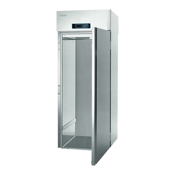
Summary of Contents for Hiber AGF 0062
- Page 1 Hiber User Manual - AGF 0062 & AGF 0072E -5/-25°C -12/-30°C -3/+10°C USER MANUAL GENERAL RECOMMENDATIONS RECEPTION AND DISPOSING OF UNIT START-UP CONTROL PANEL SETTINGS AND TROUBLE SHOOTING CLEANING AND MAINTENANCE DIMENSIONS; REFRIG. CIRCUIT DIAGRAM 6LIBL001 - 1113...
- Page 2 Equipment supplied by Italian Gelato Concepts Pty Limited PO Box 2134 Toowong Qld 4066 ABN 48 603 731 424 www.italiangelato.com.au info@italiangelato.com.au Mob: +61 (0) 411 089 142...
- Page 3 RATING PLATE 1. Manufacturer 2. Serial number 3. Code 4. Model 5. Voltage 6. Running absorbed current 7. Max refrigerant power 8. Running absorbed power 9. Defrost heating element power 10. Other elements nominal power 11. Lamp power 12. Max and min. pressure 13.
- Page 4 ENGLISH 3 Translation of the original instructions KEEP DRY STACKING OF OTHER OBJECTS ON THE APPLIANCE This appliance is designed for indoor use and should only MUST BE ABSOLUTELY AVOIDED. be used to store food and beverages. Conservation models (low temperature) have been realized to store only pre-frozen products.
- Page 5 4 ENGLISH Translation of the original instructions IMPORTANT BEFORE CONNECTING THE APPLIANCE CHECK THAT THE DATA ON THE SERIAL PLATE CORRESPOND TO THE ACTUAL ELECTRICAL SUPPLY. THE SERIAL PLATE GIVING THE ELECTRICAL DATA REQUIRED IN THE INSTALLATION IS FOUND ON THE RIGHT SIDE OF THE COMPARTMENT. An incorrect power supply could be cause of fire, electric shake or accident.
- Page 6 ENGLISH 5 Translation of the original instructions Press the SET ( ) button or do not operate for the compressor LED to go off, after which the instrument will exi t from the procedure. The keypad i s blocked by keeping pressed si m ul t aneously DO NOT PERFORM ANY MAINTAINANCE WHEN THE for a few seconds: "Loc"...
- Page 7 6 ENGLISH Translation of the original instructions When the cause that triggered the alarm is resolved, the display restores normal operation, except for the power failure alarm, which requires the normal display to be restored manually. CHAMBER TEMPERATURE Displayed with the instrument on, during normal operation. The HACCP LED provides information regarding the memory EVAPORATOR TEMPERATURE (with the evaporator probe present) status of the HACCP alarms: if it is on, not all the information...
- Page 8 ENGLISH 7 Translation of the original instructions Defrosting at intervals with d8=3; The HACCP will not provide information regarding the date and time when the alarm was triggered / The Energy To enter the procedure: Saving function is not available in real time / Alarm output activated if u1=3 •...
- Page 9 8 ENGLISH Translation of the original instructions YOU MUST FOLLOW THE INSTRUCTIONS BELOW ESPECIALLY WHEN USING R290 COOLANT CONDENSING COIL (see reference 13 on page 2 of this manual and the It is important that the coil can offer the maximum possible heat data plate on the device) exchange.
- Page 15 PARAMETERS PAR Description GL = Glass Door Working setpoint SP2 Minimum evaporator temperature durinf Overcooling phase CA1 Cabinet probe offset CA2 evaporator probe offset P1 decimal point Celsius degree unit of measure temp. P3 evaporator probe function P8 delay in display of variations in temp. detected by the probes r0 working setpoint differential r1 minimum working setpoint r2 maximum working setpoint /...
- Page 16 PAR Description 0= Intervals – defr. will be activated once the instrument run for time d0; 1= Intervals – defr. will be activated once the compressor has switched on for time d0; 2= Intervals – defr. will be activated once the evaporator temp. has altogether been below temp. d9 for time d0; 3= Adaptable - defrosting will be activated when (condition 1) the evaporator temp.
- Page 17 PAR Description funcionamiento normal 0=switched off; 1=switched on; see also F13, F14 and i10; 2=in parallel with the compr.; see also F9, F13, F14 and i10; 3=dependent on F1 [17]; 4=switched off if the compr. is switched off, dependent on F1 if the compr. is switched on; see also F9 [16]; 5=dependent on F6; see also F9 evaporator temp.
- Page 18 PAR Description Cell temp. below that at which th e door resistors are switched on (only if u1=4) Operating time of demistor resistors (only if u1=1) / u7 Cell temp. below that at which the evaporator valve is disactivat e d ( Setpoint + u7) (only if u1=5) / [7] u8 Tipe of evaporator valve contact (only if u1=5) Enabling of buzzer instrument address /...
- Page 19 ENGLISH (1) The unit of measurement depends on P2 parameter (3) Properly set the parameters corresponding to the regulators after modifying P2 parameter (4) The parameter has effect even after an interruption in the power supply that occurs while the instrument in switched on (5) The time established with the parameter is counted even when the instrument is switch off (6) If parameter C1 is set to 0, the delay after the end of the cell probe error will be 2 minutes (7) The parameter differential is 2,0 °C / 4 °F...
-
Page 20: Refrigeration Circuit Diagram
REFRIGERATION CIRCUIT DIAGRAM 1 Compressor 2 Condenser 3 Filter drier dirty 4 Capillary tube 4 Valve 5 Evaporator 6 Will be borne by the installer (remote unit versions) All specifications and data are subject to change without notice. Copyright...

Need help?
Do you have a question about the AGF 0062 and is the answer not in the manual?
Questions and answers