Table of Contents
Advertisement
Available languages
Available languages
Quick Links
Advertisement
Chapters
Table of Contents

Subscribe to Our Youtube Channel
Summary of Contents for Klarstein Klimaanlage
- Page 1 Klimaanlage 10031436...
-
Page 2: Table Of Contents
Sehr geehrter Kunde, wir gratulieren Ihnen zum Erwerb Ihres Gerätes. Lesen Sie die folgenden Hinweise sorgfältig durch und befol- gen Sie diese, um möglichen Schäden vorzubeugen. Für Schäden, die durch Missachtung der Hinweise und unsachgemäßen Gebrauch entstehen, übernehmen wir keine Haftung. Inhaltsverzeichnis Technische Daten 2 Sicherheitshinweise 2... - Page 3 Verwenden Sie das Gerät nur wenn es ordnungsgemäß geerdet ist, andernfalls kann es zu einem Stromschlag kommen. • Der gelb-grüne Draht oder der grüne Draht (je nach Modell) in der Klimaanlage ist das Erdungskabel. Ver- wenden Sie das Erdungskabel nicht für andere Zwecke.
-
Page 4: Elektrisches Anschlussdiagramm
Elektrisches Anschlussdiagramm Innengerät Raum- Sensor Anzeige- platine Schritt- LED- motor Leiter- platte Hinweis: verwenden Sie nur Kupferleiter Außengerät Außenrohr- Außen- Motor Rohr- 4-Wege- fühler sensor Innen- fühler Ventil Ventilator Schaltkasten Innen- Ventilator AP1 Hauptplatine Außen- Außen- Ventilator Ventilator1... -
Page 5: Packungsinhalt
Packungsinhalt Innengerät Stoffmanschette Unterbau- (Luftkanal) Fernbedienung Halter (Fernbedienung) Schraube (4) Senkschraube (2) (Fernbedienungs-Halter) Anleitung Blechschraube (8) Schraubkappe (6) für Innen für Außen (unten) (oben) Doppelseitig Batterien (2) Lüftungsplatte gummiertes Pad AAA 1.5V Außengerät Stromkabel Klammer (10) -
Page 6: Geräteübersicht
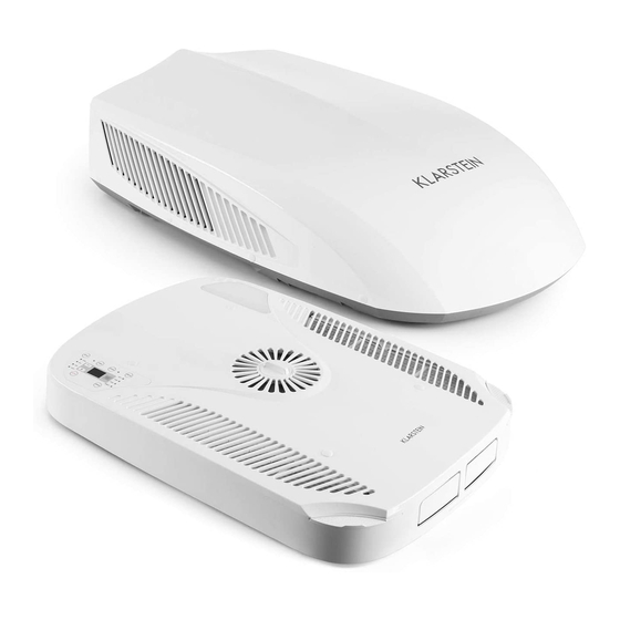
Geräteübersicht Innengerät Luftauslassgitter LED-Leuchte Filterunterbau Bedienfeld Fernbedienung (Membran) Lufteinlassgitter Außengerät Außenhülle Lufteinlassgitter Rahmen Wasserauslass... -
Page 7: Fernbedienung Und Display
Fernbedienung und Display Fernbedienungs-Tasten 1 ON/OFF Taste 2 MODE Taste (Modus) 3 [-] Taste 4 [+] Taste 5 FAN Taste (Ventilator) ] Taste (Luftstromrichtung) 7 CLOCK Taste (Uhr) 8 LED Taste 9 TIMER ON Taste (Ein-Timer) 10 TEMP Taste (Temperatur) 11 TIMER OFF Taste (Aus-Timer) 12 TURBO Taste 13 SLEEP Taste... - Page 8 Funktionsumfang verwendet werden kann. Daher kann es vorkommen, dass einigen der Funktions- tasten bei Ihrem gerät keine Funktion zugeordnet ist. • Nach dem Einschalten der Klimaanlage gibt das Gerät eine Ton von sich und die Power-Anzeige leuchtet rot. Sie können die Klimaanlage nun über die Fernbedienung bedienen.
- Page 9 Drücken Sie die Taste, um das LED-Licht am Bedienfeld ein- und auszuschalten. Nachdem Sie die Taste gedrückt haben, erscheint das Uhren-Symbol [ ] im Display und [ON] blinkt. Als Zeit wird [00:00] angezeigt. Drücken Sie innerhalb von 5 Sekunden auf [+] oder [-], um den Einschalt-Timer einzustellen.
- Page 10 Spezielle Funktionen AUTO-Modus: Wenn Sie AUTO-Modus wählen, wird die eingestellte Temperatur nicht angezeigt. Das Display zeigt in diesem Fall die aktuelle Raumtemperatur an und das Gerät wählt automatisch die richtigen Funktionen, um eine kom- fortable Raumtemperatur zu gewährleisten. TURBO-Funktion: Wenn diese Funktion starten, läuft das Gerät mit hoher Lüftergeschwindigkeit, um den Raum es schnell wie möglich abkühlen oder zu erwärmen.
-
Page 11: Bedienfeld Und Tastenfunktionen
Batterien austauschen Nehmen Sie die Deckel des Batteriefachs ab und entnehmen Sie die alten Batterien. Setzen Sie zwei neue AAA 1.5V Batterien ein und achten Sie darauf, sie richtig herum einzulegen. Schließen Sie den Deckel wieder. • Tauschen Sie immer alle Batterien aus, verwenden Sie nicht alte zusammen mit neuen Batterien. •... -
Page 12: Installation
Gerät nicht mit entfernter Abdeckung. Schritt 1: Standort auswählen und Außengerät anbringen Ihre Klimaanlage ist für den Einsatz in Wohnmobilen konzipiert. Überprüfen Sie das Dach des Fahrzeugs, um festzustellen, ob es die Last des Außen- und Innengeräts ohne zusätzliche Unterstützung tragen kann. Verge- wissern Sie sich, dass die Montagefläche vorhandenen Strukturen im Inneren nicht beeinträchtigt. - Page 13 Nachdem die Öffnung im Dach und an der Innendecke die richtige Größe hat, muss eine gerahmte Tragkonst- ruktion zwischen der äußeren Dachplatte und der inneren Decke platziert werden. Die verstärkte Rahmenkon- struktion muss den folgenden Maßen entsprechen: 1. Der Rahmen muss in der Lage sein, sowohl das Gewicht des Innen- als auch des Außengeräts zu tragen.
- Page 14 Beispiel für eine Ausgleichsstütze und Abmessungen des Außengeräts: Schritt 2: Außengerät befestigen Öffnen Sie die Verpackung und entnehmen Sie das Außengerät. Wenn Sie das Gerät entnommen ha- ben, heben Sie es nicht am oberen Luftauslass an, heben Sie es von unten an. Heben Sie das Außengerät auf das Dach des Fahr- zeugs.
- Page 15 Schritt 3: Installation des Außen- und Innengeräts Stellen Sie vor der Montage des Innengeräts sicher, dass Sie das Außengerät ordnungsgemäß auf dem Dach- angebracht haben. Bevor Sie die Schrauben fest anziehen beachten Sie folgendes: • Die maximale Dicke des Fahrzeugdachs darf zwischen 30-80 mm betragen. •...
- Page 16 Außengerät Installation der Belüftungsöffnungs- Klemme Innengerät Obere Lüftungsplatte Stoffmanschette an Stoffkanal/ der oberen Lüftungs- Stoffmanschette platte befestigen. 5. Befestigen Sie den Deckenmontagerahmen mit den Befestigungsschrauben am Außengerät (siehe Abbil- dung auf der vorherigen Seite). Drehen Sie die Befestigungsschrauben von Hand ein, damit Sie nicht schief sitzen.
- Page 17 Rahmen Untere Lüftungsplatte Stoffkanal Schrauben Achten Sie beim Einbau darauf, dass die Aussparung für die Schraube frei bleibt...
- Page 18 Schritt 4: Elektrische Anschlüsse Vergewissern Sie sich, dass die Stromzufuhr zum Gerät unterbrochen ist, bevor Sie Arbeiten am Gerät durch- führen, um Stromschläge oder Verletzungen oder Schäden am Gerät zu vermeiden. Nach dem ordnungsge- mäßen Befestigen des Deckenmontagerahmens am Außengerät sind folgende elektrische Anschlüsse vorzu- nehmen: 1.
- Page 19 Mögliche Steckverbindungen (abhängig vom Modell): Schritt 5: Installation abschließen Um die Installation ordnungsgemäß anzuschließen, müssen die folgenden Schritte ausgeführt werden: • Überprüfen Sie die Position des Thermostats. Stellen Sie sicher, dass der Thermostat durch die Halterung geführt wird und keine Metalloberfläche berührt. •...
-
Page 20: Fehlersuche Und Fehlerbehebung
Seite zu Seite so eben wie möglich aus, wenn das Fahrzeug geparkt ist. Stellen Sie sicher, dass die Klimaanlage korrekt montiert ist und eben steht. Die Temperatur ist zu hoch Stellen Sie eine niedrigere Temperatur ein. - Page 21 So entnehmen Sie den Luftfilter Entnehmen Sie die Luftfilter, wie auf der unteren Abbildung abgebildet: So reinigen Sie die Luftfilter Waschen Sie den Staub mit sauberem Wasser von den Luftfiltern oder saugen Sie die Filter mit einem elekt- rischen Staubsauger ab. So entfernen Sie die Klammern 1.
- Page 22 2. Skizze eines Werkzeugs zum Entfernen der Klammer: 3. Mögliche Zustände der Klammer: Klammerkern Klammerbasis ca. 3mm Vorher Hinterher Abmontiert...
-
Page 23: Hinweise Zur Entsorgung
Hinweise zur Entsorgung Befindet sich die linke Abbildung (durchgestrichene Mülltonne auf Rädern) auf dem Pro- dukt, gilt die Europäische Richtlinie 2012/19/EU. Diese Produkte dürfen nicht mit dem nor- malen Hausmüll entsorgt werden. Informieren Sie sich über die örtlichen Regelungen zur getrennten Sammlung elektrischer und elektronischer Gerätschaften. -
Page 24: Technical Data
Dear Customer, Congratulations on purchasing this equipment. Please read this manual carefully and take care of the following hints to avoid damages. Any failure caused by ignoring the mentioned items and cautions mentioned in the instruction manual are not covered by our warranty and any liability. Contents Technical Data 24 Safety Instructions 24... - Page 25 Hints on Location Installing the unit in the following places may cause malfunction. If it is unavoidable, please consult the local dealer: • The place with strong heat sources, vapors, flammable or explosive gas, or volatile objects spread in the air. •...
-
Page 26: Electric Diagram
Electric Diagram Ceiling Assembly ROOM SENSOR DISPLAY BOARD STEPPING STEPPING MOTOR MOTOR BOARD Notice: Use Copper Conductors Only Roof Top Air Conditioner OUTDOOR TUBE OUTROOM IN_FAN 4-WAY TUBE SENSOR SENSOR SENSOR MOTOR VALVE ELECTRIC BOX IN_FAN AP1 MAIN BOARD OUT FAN OUT FAN1... -
Page 27: Packing Content
Packing Content Indoor Unit Sponge Bolt (air duct) Remote Control Holder (Remote control) sub-assy (4) Sunk screw (2) (remote controller holder) Manual Tapping screw (8) Screw cap (6) use in use in indoor outdoor (bottom) (upper) Double-sided battery (2) Plate of air vent gummed paper AAA 1.5V Outdoor Unit... -
Page 28: Product Description
Product Description Indoor Unit Air-outgrille LED indicator Filter sub-assy Control panel Remote controller (membrane) Air-in grille Outdoor Unit Outer case Air-in grille Chassis Drainage outlet... -
Page 29: Remote Control And Display
Remote Control and Display Controls 1 ON/OFF button 2 MODE button e -button 3 [+] button 4 FAN button ] button 7 CLOCK button 8 LED button 9 TIMER ON button 10 TEMP button 11 TIMER OFF button 12 TURBO button 13 SLEEP button 14 LIGHT button Display... - Page 30 Functions in Detail • This is a general use remote controller, it could be used for the air conditioners with multifunction; For some function, which the model doesn‘t have, if press the corresponding button on the remote controller that the unit will keep the original running status.
- Page 31 Press this button can turn on or turn off the LED light on the panel. Timer On setting: Signal „ON“ will blink and display, signal [ ] 9will conceal, the numerical section will become the timer on setting status. During 5 seconds blink, by pressing + or - button to adjust the time value of numerical section, every press of that button, the value will be increased or decreased 1 minute.
- Page 32 Special Functions About AUTO RUN When AUTO RUN mode is selected, the setting temperature will not be displayed on the LCD, the unit will be in accordance with the room temp. automatically to select the suitable running method and to make ambient comfortable.
-
Page 33: Control Panel And Controls
Replacement of Batteries Remove the battery cover plate from the rear of the remote controller. Take out the old batteries. Insert two new AAA1.5V dry batteries, and pay attention to the polarity. Reinstall the battery cover plate. • When replacing the batteries, do not use old or different types of batteries, otherwise, it may cause malfunction. •... -
Page 34: Installation
Installation Before Installation • Testrun the unit with proper power supply. • Refer to the operation instruction section in the Owner‘s Manual Operation & Installation. Make sure all the controls operate cor- rectly then disconnect the power supply of the unit. •... - Page 35 After the opening in the roof and interior ceiling are the correct size,a framed support structure must be placed between the exterior roof top and interior ceiling. The reinforced framed structure must follow the follwing guidelines: 1. It must be capable of supporting both the weight of the roof top air conditioner and the interior ceiling assembly.
- Page 36 Height varies to make Unit level: Dimensions: Step 2: Mounting Outdoor Unit 0pen the package and take out the outdoor unit. When taking out the outdoor unit after unpacking, do not lift the air outlet grille at the back of outer case.
- Page 37 Step 3: Installing the Ceiling Assembly Make sure that you have properly matched the roof top air conditioner and interior ceiling assembly.Caution before tightening bolts: • The applicable thickness of vehicle roof ranges from 30mm-80mm. • Before tightening bolts, screw in the four bolts manually and prohibit screwing forcibly. •...
- Page 38 Outdoor Unit Installation way of ventilation clamp Indoor Unit Upper Duct Plate This should Fabric Duct be assembled 5. Secure the ceiling assembly frame to the roof top air conditioner with the mounting bolts(see Figure 5).You must start (thread) themounting bolts by hand to avoid cross-threading. DO NOT START THE MOUNT- ING BOLTS WITH AN AIR GUN.
- Page 39 Frame Bottom Duct Plate Fabric Duct Screws Pay attention to match the gap with the riveted nut during installation...
- Page 40 Step 4: Electrical Wiring Make sure that all power supply to the unit is disconnected before performing any work on the unit to avoid the possibility of shock or injury and/or damage to the equipment. After the interior ceiling assem- bly frame is properly secured to the roof top air conditioner, the following electrical connections must be performed.
- Page 41 Possible plug-in connections (depending on the model): Step 5: Completing the Installation To complete the installation and system checkout requirements, the following steps must be performed: • Check the thermostat position. Make sure the thermostat is routed through the holding guide and is not touching any metal surface.
-
Page 42: Troubleshooting
Troubleshooting Trouble Possible Cause Solution The unit can not start. The unit may not be connected to Check the power supply of the vehicle and the power supply correctly. make sure it is provided correctly. The unit can not cool The roof top air conditioner is not Mount the roof top air conditioner as level as the room. - Page 43 How to Remove the Air Filter Remove the air filters by pulling them as illustrated below: How to clean the Air Filter Wash away dust from the air filters with clean water or vacuum the filter with an electric household vacuum cleaner.
- Page 44 2. Sketch map of claspdismantle tool: 3. Sketch map of clasp in different status: Clasp core Clasp base about Before After Demountable statuss...
-
Page 45: Hints On Disposal
Hints on Disposal According to the European waste regulation 2012/19/EU this symbol on the product or on its packaging indicates that this product may not be treated as household waste. In- stead it should be taken to the appropriate collection point for the recycling of electrical and electronic equipment. -
Page 46: Fiche Technique
Chère cliente, cher client, Toutes nos félicitations pour l’ a cquisition de ce nouvel appareil. Veuillez lire attentivement et respecter les instructions de ce mode d’ e mploi afin d’ é viter d’ é ventuels dommages. Nous ne saurions être tenus pour res- ponsables des dommages dus au non-respect des consignes et à... - Page 47 Remarques sur le lieu d’installation L’installation de l’ a ppareil dans les lieux suivants peut provoquer des dysfonctionnements. Si cela était toute- fois inévitable, contacter une entreprise spécialisée sur place : • Les lieux comportant de fortes sources de chaleur, des vapeurs, des gaz inflammables et explosifs ou des objets volatiles susceptibles de se propager dans l’...
-
Page 48: Schéma Des Branchements Électriques
Schéma des branchements électriques Appareil intérieur Capteur ambiant Platine d’affichage Moteur Circuit pas-à- imprimé Remarque : utiliser uniquement des fils en cuivre Appareil extérieur Capteur Capteur Capteur Ventilateur de conduit Soupape à extérieur interne du conduit extérieur 4 voies moteur Armoire de commande Ventilateur... -
Page 49: Contenu De L' E Mballage
Contenu de l’ e mballage Appareil intérieur Manchon souple Vis de Télécommande (canal d’ a ir) Support (télécommande) soutien (4) Vis à tête fraisée (2) (Support de télécom- Mode d’ e mploi Vis Parker (8) Bouchon vissable (6) mande) Pour Pour l’intérieur l’... -
Page 50: Aperçu De L' A Ppareil
Aperçu de l’ a ppareil Appareil intérieur Grille d’évacuation d’air Voyant LED Support de filtre Panneau de Télécommande commande (membrane) Grille d’évacuation d’air Appareil extérieur Coque extérieure Grille d’arrivée d’air Cadre d’eau... -
Page 51: Télécommande Et Écran
Télécommande et écran Touches de la télécommande 1 Touche ON/OFF 2 Touche MODE (mode) 3 Touche [-] 4 Touche [+] 5 Touche FAN (ventilateur) 6 Touche [ ] (direction du flux d’ a ir) 7 Touche CLOCK (heure) 8 Touche LED 9 Touche TIMER ON (démarrage différé) 10 Touche TEMP (température) 11 Touche TIMER OFF (éteinte différée) - Page 52 Détail des fonctions de la télécommande • La télécommande est une télécommande classique qui peut être utilisée pour différents climatiseurs avec diverses fonctionnalités. De fait, il peut arriver que certaines touches de commande soient inactives avec certains appareils. • Après le démarrage du climatiseur, l’ a ppareil produit un signal sonore et le voyant de marche s’ a llume en rouge.
- Page 53 Appuyer sur cette touche pour allumer ou éteindre la lumière LED du panneau de com- mande. Une fois cette touche appuyée, le symbole de l’horloge [ ] apparaît à l’ é cran et [ON] cli- gnote. Le temps affiché est [00:00]. Appuyer sur [+] ou [-] sous les 5 secondes pour régler le démarrage différé.
- Page 54 Fonctions spéciales Mode AUTO : Lorsque le mode AUTO est sélectionné, la température paramétrée ne s’ a ffiche pas. L’ é cran affiche dans ce cas la température ambiante actuelle et l’ a ppareil sélectionne automatiquement les fonctions adaptées pour garantir une température ambiante confortable.
-
Page 55: Panneau De Commande Et Fonctions Des Touches
Remplacement des piles Enlever le couvercle du compartiment des piles et retirer les anciennes piles. Introduire deux nouvelles piles AAA 1,5 V et veiller à les introduire dans le bon sens. Puis refermer le couvercle. • Toujours remplacer toutes les piles en même temps, ne pas utiliser d’ a nciennes piles avec de nouvelles. •... -
Page 56: Installation
Installation Avant l’installation • Brancher l’ a ppareil sur une prise et tester les modes et les fonc- tions. • S’ a ssurer que toutes les touches fonctionnent correctement. • Rebrancher ensuite l’ a ppareil à l’ a limentation électrique. •... - Page 57 Une fois que l’ o uverture dans le toit et que le plafond intérieur ont la taille correcte, il est nécessaire de monter une construction de soutien entre la plaque du toit extérieur et le plafond intérieur. La structure de renforce- ment construite doit correspondre aux mesures suivantes : 1.
- Page 58 Exemple de support de rééquilibrage et dimensions de l’ a ppareil extérieur : Étape 2 : fixer l’ a ppareil extérieur Ouvrir l’ e mballage et sortir l’ a ppareil extérieur. Une fois l’ a ppareil sorti, ne pas le soulever par la sortie d’...
- Page 59 Étape 3 : installation des appareils extérieur et intérieur S’ a ssurer avant le montage de l’ a ppareil intérieur que l’ a ppareil extérieur est correctement monté sur le toit. Avant de visser les vis, respecter les consignes suivantes : •...
- Page 60 Appareil extérieur Installation des attaches de l’ o uverture d’ a ération Appareil intérieur Plaque d’ a ération du dessus Fixer le manchon à la Conduit en tissu/ plaque d’ a ération du manchon en tissu dessus 5. Fixer le cadre de montage du plafond à l’ a ppareil extérieur avec des vis de fixation (cf. illustration de la page précédente).
- Page 61 Cadre Plaque d’ a ération du dessous Conduit en tissu Lors du montage, veiller à laisser l’ e ncoche prévue pour la vis dégagée.
- Page 62 Étape 4 : branchements électriques S’assurer que l’alimentation électrique de l’appareil est coupée avant de commencer toute intervention sur l’appareil pour éviter toute électrocution ou toute blessure ou tout dégât sur l’appareil. Une fois que le cadre de montage du plafond est fixé à l’appareil extérieur, effectuer les branchements électriques suivants : Cadre 1.
- Page 63 Branchements possibles (selon le modèle) : Étape 5 : terminer l’installation Pour terminer correctement l’installation, procéder aux étapes suivantes : • Vérifier la position du thermostat. S’ a ssurer que le thermostat passe bien par le support et qu’il ne touche aucune surface en métal.
-
Page 64: Identification Et Résolution Des Problèmes
Identification et résolution des problèmes Problème Cause possible Solution L’ a ppareil ne L’ a ppareil n’ e st pas correctement Vérifier la source d’ a limentation électrique du fonctionne pas. branché à la source d’ a limentation véhicule et les branchements. électrique. - Page 65 Voici comment retirer le filtre à air Retirer le filtre à air comme illustré ci-dessous : Voici comment nettoyer le filtre à air Enlever la poussière des filtres à air à l’ e au propre ou aspirer la poussière des filtres avec un aspirateur électrique. Voici comment retirer les attaches 1.
- Page 66 2. Schéma d’un outil pour le retrait de l’ a ttache. 3. Positions possibles de l’ a ttache Centre de l’ a ttache Socle de l’ a ttache env. 3 mm Avant Après Démonté...
-
Page 67: Information Sur Le Recyclage
Information sur le recyclage Vous trouverez sur le produit l’image ci-contre (une poubelle sur roues, barrée d‘une croix), ce qui indique que le produit se trouve soumis à la directive européenne 2012/19/UE. Renseignez-vous sur les dispositions en vigueur dans votre région concernant la collecte séparée des appareils électriques et électroniques. -
Page 68: Datos Técnicos
Estimado cliente, Le felicitamos por la adquisición de este producto. Lea atentamente el siguiente manual y siga cuidadosamen- te las instrucciones de uso con el fin de evitar posibles daños. La empresa no se responsabiliza de los daños ocasionados por un uso indebido del producto o por haber desatendido las indicaciones de seguridad. Índice Datos técnicos 68 Indicaciones de seguridad 68... - Page 69 Indicaciones sobre el lugar de instalación La instalación del aparato puede provocar fallos en el funcionamiento en los siguientes emplazamientos. Si es inevitable, contacte con un servicio técnico de su zona: • En lugares con fuentes de calor potentes, vapores, gases inflamables o explosivos u objetos en suspensión que pudieran distribuirse en el aire.
-
Page 70: Diagrama De Conexiones Eléctrico
Diagrama de conexiones unidad interior sensor de la estancia Anzeige- platine motor placa paso a conduc- paso tora LED advertencia: utilice solo cables de cobre unidad exterior sensor del sensor conducto sensor motor sensor del exterior de exterior exterior conducto ventilador 4 válvulas interior... -
Page 71: Contenido Del Paquete
Contenido del paquete Dispositivo interior Tornillo para Esponja empotrar (conducto de aire) Mando a distancia Soporte (Mando a distancia) aparato (4) Tornillo avellanado (2) Tornillo para (Soporte del mando a Tapón con rosca (6) chapa (8) distancia) Instrucciones para para interior exterior (abajo) -
Page 72: Descripción Del Aparato
Descripción del aparato Unidad interior Rejilla de salida de aire Luz LED Base del filtro panel de control Mando a distancia (membrana) Rejilla de la entra- da de aire Unidad exterior Carcasa exterior Rejilla de la entrada de aire Marco Desagüe... -
Page 73: Mando A Distancia Y Display
Mando a distancia y display Botones del mando a distancia 1 Botón ON/OFF 2 Botón MODE (modo) 3 Botón [-] 4 Botón [+] 5 Botón FAN (ventilador) 6 Botón [ ] ] (orientación corriente de aire) 7 Botón CLOCK (reloj) 8 Botón LED 9 Botón TIMER ON (temporizador de encendido) 10 Botón TEMP (temperatura) - Page 74 Funciones en detalle del mando a distancia • El mando a distancia es un modelo estándar que puede utilizarse para distintos climatizadores con tipos de funcionamiento diferente. Por ello puede ocurrir que algunos botones no tengan asignada ninguna función para su aparato. •...
- Page 75 Pulse el botón para encender y apagar la luz LED. Después de haber pulsado el botón, aparece el símbolo del reloj [ ] en el display y [ON] parpadea. En la hora aparece [00:00]. Pulse en los siguientes 5 segundos [+] o [-] para ajustar el temporizador de encendido.
- Page 76 Funciones especiales Modo AUTO: Si selecciona el modo AUTO, no aparecerá la temperatura configurada. En este caso, el display muestra la temperatura ambiente actual y el aparato selecciona automáticamente las funciones correctas para garantizar una temperatura ambiente agradable. Función TURBO: Si inicia esta función, el aparato funciona con la velocidad del ventilador más elevada para refrigerar o calentar la estancia lo más rápidamente posible.
-
Page 77: Panel De Control Y Funciones De Los Botones
Sustituir pilas Extraiga la tapa del compartimento para las pilas y retire las pilas usadas. Introduzca dos pilas nuevas AAA 1.5 V y asegúrese de que se hayan colocado conforme a la polaridad correcta. Cierre la tapa. • Sustituya siempre todas las pilas, no mezcle pilas nuevas con usadas. •... -
Page 78: Instalación
Instalación Antes de la instalación • Conecte el aparato a una toma de corriente y pruebe los modos y funciones. • Asegúrese de que todos los botones funcionan correctamente. • Desconecte el aparato del suministro eléctrico. • Antes de la instalación, compruebe que las tres almohadillas de goma se encuentra en la junta cuadrada del aparato (consulte imagen). - Page 79 Después de que el orificio en el techo y en el techo interior tengan el tamaño adecuado, deberá colocarse una estructura demarcada entre el exterior del techo y el techo interior. El marco de refuerzo deberá contar con las medidas siguientes: 1.
- Page 80 Ejemplo de un nivelador y dimensiones de la unidad exterior: Paso 2: Fijar unidad exterior Abra el embalaje y retire la unidad exterior. Cuando haya retirado el aparato, no lo levante por la salida de aire superior, sino por la parte inferior. Levante la unidad exterior hasta el techo del vehí- culo.
- Page 81 Paso 3: Instalación de la unidad exterior e interior Antes del montaje, asegúrese de que la unidad exterior se ha montado correctamente en el techo. Antes de apretar los tornillos, tenga en cuenta lo siguiente: • El grosor máximo del techo del vehículo debe situarse en 30-80 mm. •...
- Page 82 unidad exterior instalación de la abra- zadera de ventilación unidad interior placa de ventilaci- ón superior fijar conducto es- conducto ponjoso a la placa de esponjoso ventilación 5. Fije el marco de montaje de techo con los tornillos de fijación a la unidad exterior (véase ilustración de la página anterior).
- Page 83 Marco placa de ventilación inferior conducto esponjoso tornillos En el montaje tenga en cuenta que queden orificios para los tornillos...
- Page 84 Paso 4: Conexiones eléctricas Asegúrese de que el suministro de electricidad al aparato esté interrumpida antes de realizar cu- alquier trabajo en el aparato para evitar descargas eléctricas, lesiones o averías. Después de haber fijado correctamente el marco de montaje de techo a la unidad exterior, realice las siguientes cone- xiones eléctricas: 1.
- Page 85 Posibles conexiones (dependiendo del modelo): Paso 5: Finalizar instalación Para conectar la instalación correctamente, debe seguir estos pasos: • Compruebe la posición del termostato. Asegúrese de que el termostato pase por el soporte y no entre en contacto con superficies metálicas. •...
-
Page 86: Detección Y Resolución De Problemas
Detección y resolución de problemas Problema Posible causa Solución El aparato no funciona. El aparato no está conectado Compruebe el suministro eléctrico del correctamente al suministro vehículo de las conexiones. eléctrico. El aparato no enfría La unidad exterior no está recta. Oriente la unidad exterior de adelante hacia correctamente. - Page 87 Cómo extraer el filtro de aire Retire el filtro de aire como se indica en la ilustración inferior: Cómo limpiar el filtro de aire Quite el polvo con agua fresca del filtro o aspire este último con una aspiradora eléctrica. Cómo retirar las pinzas 1.
- Page 88 2. Esquema de la herramienta para retirar la pinza: 3. Posible estado de la pinza centro de la pinza base de la pinza aprox antes después desmontada...
-
Page 89: Indicaciones Para La Retirada Del Aparato
Indicaciones para la retirada del aparato Si el aparato lleva adherida la ilustración de la izquierda (el contenedor de basura tachado) entonces rige la normativa europea, directiva 2012/19/UE. Este producto no debe arrojar- se a un contenedor de basura común. Infórmese sobre las leyes territoriales que regulan la recogida separada de aparatos eléctricos y electrónicos. -
Page 90: Dati Tecnici
Gentile cliente, La ringraziamo per aver acquistato il nostro prodotto. La preghiamo di leggere attentamente le seguenti istru- zioni e di seguirle per evitare eventuali danni. Si declina ogni responsabilità per danni derivati da una mancata osservazione delle avvertenze di sicurezza e da un uso improprio del dispositivo. Indice Dati tecnici 90 Avvertente di sicurezza 90... - Page 91 Note per il luogo di installazione L´installazione del dispositivo nei luoghi sottoelencati può comportare dei malfunzionamenti. Se non si hanno alternative, si prega di rivolgersi ad una persona specializzata: • In un luogo dove sono presenti fonti di calore, vapori, gas infiammabili o esplosivi che possono diffondersi nell‘aria.
-
Page 92: Diagramma Di Collegamento Elettrico
Diagramma di collegamento elettrico Dispositivo interno Sensore stanza Scheda display Motore Circuito passo- stampa- passo to LED Nota: utilizzare solo conduttori in rame Dispositivo esterno Sensore tubo Sensore Motore Sensore Valvola a esterno esterno ventilatore tubo 4 vie interno Quadro elettrico Ventilatore interno AP1 Scheda principale... -
Page 93: Consegna
Consegna Dispositivo interno Condotto aria Vite (4) Telecomando Supporto telecomando Vite Vite a testa svasata (sup- autofilettante (8) porto telecomando) (2) Istruzioni Tappo a vite (6) l´interno l´esterno (in basso) (in alto) Pad in gomma Pile (2) Piastra di ventilazione doppio AAA 1.5V Dispositivo esterno... -
Page 94: Descrizione Del Prodotto
Descrizione del prodotto Dispositivo interno Griglia scarico aria Luce a LED Filtro base Pannello dei co- Telecomando mandi (membrana) Griglia ingresso aria Dispositivo esterno Rivestimento esterno Griglia ingresso aria Telaio Uscita acqua... -
Page 95: Telecomando E Display
Telecomando e display Tasti del telecomando 1 ON/OFF 2 MODE (Modalità) 3 Tasto [-] 4 Tasto [+] 5 Tasto FAN (ventilatore) 6 Tasto [ ] (direzione flusso aria) 7 Tasto CLOCK (orario) 8 Tasto LED 9 Tasto TIMER ON (Timer On) 10 Tasto TEMP (Temperatura) 11 Tasto TIMER OFF (Timer Off) 12 Tasto TURBO... - Page 96 Funzioni del telecomando in dettaglio • Il telecomando è universale e può essere utilizzato con vari climatizzatori con caratteristiche diverse. Pertan- to può accadere che alcuni dei tasti non abbiamo alcuna funzione. • Dopo aver acceso il climatizzatore, il dispositivo emette un segnale acustico e la spia di alimentazione diven- ta rossa.
- Page 97 Premere il tasto per accendere/spegnere la luce a LED sul pannello dei comandi. Dopo aver premuto il tasto, appare il simbolo dell´orologio sul display [ ] ] e [ON] lam- peggia. Il tempo indicato è [00:00]. Premere [+] oppure [-] entro 5 secondi per impostare il timer di accensione.
- Page 98 Funzioni speciali Modalità AUTO: In modalità AUTO la temperatura impostata non viene visualizzata. In questo caso il display indica la tempera- tura ambiente attuale e il dispositivo seleziona automaticamente le funzioni che garantiscono una temperatura ambiente confortevole. Funzione TURBO: Con questa funzione il dispositivo è in funzione a velocità elevata raffredda o riscalda l´ambiente rapidamente. Utilizzo generale 1.
-
Page 99: Pannello Dei Comandi E Tasti Funzione
Sostituire le pile Rimuovere il coperchio del vano pile e togliere le pile vecchie. Inserire due pile nuove AAA 1.5 V e assicurarsi che siano inserite correttamente. Chiudere di nuovo il coperchio. • Sostituire sempre tutte le pile, non mischiare pile vecchie e pile nuove. •... -
Page 100: Installazione
Installazione Prima dell´installazione • Collegare il dispositivo ad una presa e provare le modalità e le funzioni. • Assicurarsi che tutti i tasti funzionino correttamente. • Staccare di nuovo il dispositivo dalla corrente. • Verificare prima dell´installazione che i tre pad in gomma e la guarnizione quadrata si trovino sul dispositivo (vedere la figura). - Page 101 Una volta che l´apertura sul tetto e all´interno del tetto sono della grandezza corretta, collocare una struttura di supporto con cornice di rinforzo tra il pannello del tetto esterno e quello interno. La struttura di rinforzo deve avere le seguenti dimensioni: 1.
- Page 102 Esempio di supporto di bilanciamento e dimensioni del dispositivo esterno: Fase 2: Fissare il dispositivo esterno Aprire la confezione e rimuovere il dispositivo es- terno. Quando si rimuove il dispositivo esterno, non sollevarlo tramite la griglia di uscita dell´aria, bensì sollevarlo dal basso.
- Page 103 Fase 3: Installazione del dispositivo interno ed esterno Prima del montaggio assicurarsi che il dispositivo esterno sia installato correttamente sul tetto. Prima di serrare le viti, prestare attenzione a quanto segue: • Lo spessore massimo del tetto del veicolo deve essere compreso tra 30-80 mm. •...
- Page 104 Dispositivo esterno Installazione del morsetto di ventilazione Dispositivo interno Piastra di ventilazione superiore Assemblare il con- Condotto dotto alla piastra di ventilazione superiore 5. Fissare il telaio di montaggio del tetto al dispositivo esterno utilizzando le viti di fissaggio (vedere la figura nella pagina precedente).
- Page 105 Telaio Piastra ventilazione inferiore Condotto Viti Prestare attenzione durante l´installazione che la fessura per la vite rimanga libera...
- Page 106 Fase 4: collegamenti elettrici Accertarsi di aver staccato la corrente prima di eseguire dei lavori sul dispositivo per evitare il pericolo di scosse elettriche, di infortuni o di danni al dispositivo. Dopo aver fissato correttamente il telaio per il montaggio al dispositivo esterno, eseguire i seguenti collegamenti elettrici: Telaio 1.
- Page 107 Collegamenti possibili (in base al modello): Fase 5: Completare l´installazione Per un´installazione corretta, seguire la seguente procedura: • Controllare la posizione del termostato. Assicurarsi che il termostato sia condotto attraverso il supporto e che non tocchi superfici metalliche. • Assicurarsi che le prese d‘aria ed i filtri siano posizionati in modo corretto nella griglia di ventilazione. •...
-
Page 108: Ricerca E Risoluzione Dei Problemi
Ricerca e risoluzione dei problemi Problema Causa possibile Soluzione Il dispositivo non Il dispositivo non è collegato Verificare la fonte della corrente del veicolo e funziona. correttamente alla corrente. i collegamenti. Il dispositivo Il dispositivo esterno non è Il dispositivo esterno deve essere a non raffredda collocato su una superficie piana. - Page 109 Rimuovere il filtro dell´aria Rimuovere il filtro dell´aria come rappresentato nella figura in basso: Pulire il filtro dell´aria Rimuovere la polvere con acqua pulita dai filtri dell´aria oppure aspirare i filtri con un aspirapolvere. Rimuovere i morsetti 1. Utilizzare un attrezzo simile a quello nella figura a destra. Direzionare la punta nel foro di apertura e inserire la punta nel morsetto.
- Page 110 2. Strumento per rimuovere il morsetto: 3. Stato possibile dei morsetti: Parte centrale morsetto Base morsetto ca. 3mm Prima Dopo Disassemblato...
-
Page 111: Smaltimento
Smaltimento Se sul prodotto è presente la figura a sinistra (il cassonetto dei rifiuti mobile sbarrato), si applica la direttiva europea 2012/19/UE. Questi prodotti non possono essere smaltiti con i rifiuti normali. Informarsi sulle disposizioni vigenti in merito alla raccolta separata di dis- positivi elettrici ed elettronici.
Need help?
Do you have a question about the Klimaanlage and is the answer not in the manual?
Questions and answers