
Subscribe to Our Youtube Channel
Related Manuals for Rotek ED4-5 Series


Summary of Contents for Rotek ED4-5 Series
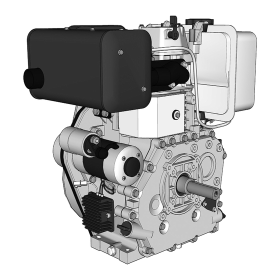
- Page 1 Air-cooled single cylinder diesel engine ED4-5 series User and maintenance manual EN L1812 version March 2019 ED4-0474-5...
- Page 2 This manual may not be reproduced in any form, neither partially nor completely, using any electronic or mechanical means whatsoever, without permission in written form by Rotek. Ignoring this is a viola- tion of copyright laws and will be prosecuted. All rights, particularly the right of reproduction, reserved.
-
Page 3: Table Of Contents
Index 1. Safety Instructions 5. Usage 1.1. Equipment 5.1. Components 5.2. Information about engine performance 1.2. Risks from noise development 5.3. Information about starter battery (optional) 1.3. Risks posed by moving parts 5.4. Check-ups before every start-up 1.4. Risks posed by gas emissions 5.4.1. -
Page 4: Safety Instructions
Do not linger around a running engine and always wear ear protection. expressly approved by ROTEK. The engine must never be operated without a muffler/exhaust system. Exhaust gases are toxic. They can cause loss of consciousness or even death. -
Page 5: Transportation And Storage
2. Transportation and storage 2.3. Prolonged downtime/Storage 2.3.1. From 30 days to 6 months 2.1 Transportation for assembly If a previously used device is to be stored for longer than 30 days Incorrect handling can cause serious damage to the device. follow these instructions: •... -
Page 6: Specification
Fuel You cannot use fuels other than regular diesel such as biodiesel, plant oil or heating oil without changing the engine! Never use fuels other than standard diesel without clearing with ROTEK first. Your engine could be damaged! We would like to point out that in Western Europe it is mandatory to mix biodiesel into available diesel fuels. Because of this mix, the “normal” diesel only keeps about 6 months in storage! After about 6 months microbial growth increases considerably in the diesel. -
Page 7: Derating Chart For Operation Under Different Conditions
3.2. Derating chart for operation under different conditions Ambient temperature (°C) Operate at sea- height (m) 1.00 1.00 1.00 1.00 1.00 1.00 1.00 1.00 1.00 0.94 0.85 0.76 0.67 1.00 1.00 1.00 1.00 1.00 1.00 1.00 1.00 1.00 0.91 0.82 0.73 0.64 1000... -
Page 8: Flange And Shaft Dimensions
3.4. Flange and shaft dimensions ED4-0474 MOTORWELLE KW1“x88 (F1) MOTORWELLE KW25x88 (F2) 15,8 15,8 MOTORWELLE TP26x77 (FG2) MOTORWELLE TP1“x105 (FG1) 3:16 48,7 31,3 105,3 14-M8-6H Tiefe 15... -
Page 9: Installation
4. Installation 4.3. Motor mounting The motor assembly must be done through four montage holes in the The installation has to be done by professionals. Poor installation can base plate. A mechanical assembly using the motor flange is not al- damage the device (ex. -
Page 10: Coupling
4.6. Coupling You can use two measure-devices to set up parallelism and coaxal at the same time. While turning the shaft slowly deviations can be mea- Before the motor can be connected to a load their compatibility sured precisely. needs to be checked! It is important to check •... -
Page 11: Concluding Mechanical Installation Instructions
4.7. Concluding mechanical installation instructions 4.8.2. Type “C” – for constant speed After the first start-up the correct alignment is to be checked while the This speed controller is made for fixed speed and is usually used motor is as warm as it usually is while operating.. as a speed controller for generators. -
Page 12: Circuit Diagram Of Starter-Dynamo
4.9.3. Circuit diagram of starter-dynamo 4.9.4.2. Oil-pressure sensor with magnetic valve Motors in versions "E" are delivered with preassembled dynamo, Optionally, you can use an injection pump with an integrated mag- loading regulator and electric starter. netic valve in the series ED4-0306 and ED4-0418. This magnetic valve can be connected to the oil-pressure-sensor in Dynamo (mounted behind flywheel) -
Page 13: Usage
5. Usage 5.2. Information about engine performance The performance refer to standard conditions (0m sea level, +25°C 5.1. Components ambient temperature). For higher temperature or usage at higher sea level it is necessary to calculate a derating of the maximum perfor- Tank cover mance (see 3.3). -
Page 14: Fuel
Never use fuels other fixed properly to a stable mounting frame. than standard diesel without clearing with ROTEK first. Your engine could be damaged! • Vent the injection nozzle, as explained in 5.4.3. -
Page 15: Hand Start (All Versions)
5.5.2.1. Hand start (all versions) • Pull the recoil-starter slowly until you feel some resistance. Bring the recoil handle slowly back. • Press the decompressor lever. • Pull the recoil handle hard and fast. • Repeat until the motor starts up.. 5.5.2.2. -
Page 16: Maintenance
6. Maintenance 6.5.1 Changing the engine oil Always check the oil level before starting up! There are marks on the Regular service and maintenance prolongs the life-span of your de- dipstick marking the minimum and maximum – when the device is vice and enables an undisturbed user experience. -
Page 17: Cleaning And Exchanging The Air Filter
6.5.2 Cleaning and exchanging the air filter 6.5.3.2. Ventilating the injection system If the air filter is lose or dirty the engine performance will be low (ex. see 5.4.3. motor produces black gas under load). Therefor you must always After the device stood still for a long time it is possible that the piston change the filter according to the maintenance intervals. -
Page 18: Proper Timing/Adjusting The Valves
6.5.4. Proper timing/adjusting the valves 6.5.5. Governing behaviour Improper valve clearance is noticeable by restless engine run, back- The mechanical governer can be influenced in its regulation in diffe- fire or low performance. rent ways. The governing (how much the actual speed deviates from the ideal speed) and the oscillating (engine speed oscillates arround In order to set up the valves follow these instructions: ideal speed) are important. -
Page 19: General Tightening Torque
6.5.8. General tightening torque Dynamo (mounted behind flywheel) Torque [ Nm ±5% ] High Electric Tension rod Strength Strength Electric starter Loading regulator Battery(+) ≥2,5mm² screws which don’t have to be so hard (screws in alluminium, mounting screws external parts, flywheel cover, etc.) Starter relais ≥2,5mm²... -
Page 20: Maintenance Intervals
6.6. Maintenance intervals before after each 1600 hours hours hours hours hours start (Initial) month month month month Refuel Fuel Check the fuel tube for leaks Change the fuel filter Check oil level Check whether any oil is leaking ... -
Page 21: Possible Errors And Their Solutions
6.7. Possible errors and their solutions 6.7.1. Engine does not start Problem Cause Solution main switch switched off Turn on the main switch Charge battery externally and check the state of the battery Battery broken or too weak again. Electrical problem in option “E” Check the battery cables to the starter as well as the control Wiring damaged or loose cables to the starting relais... -
Page 22: Low Engine Performance
6.7.3. Low engine performance Problem Cause Solution Bad air supply Air filter or air intake clogged Clean or replace air filter, air housing and intake manifold Refuel tank Too less fuel in tank - no continous fuel supply Check injection pump and fuel tubes Air in fuel system Ventilate fuel system Wrong fuel... -
Page 23: List Of Parts/Exploded Assembly Drawing
6.8. List of parts/exploded assembly drawing 6.8.1. Crankcase 113 114 1106 1108 1107 1102 1151 1113 Rotek order nr. Rotek order nr. Description pcs. ED4-0219 ED4-0306 ED4-0474 Description pcs. ED4-0219 ED4-0306 ED4-0474 Oil drain screw Air guide Oil drain gasket... -
Page 24: Cylinder Head
6.8.2. Cylinder head Rotek order nr. Rotek order nr. Description pcs. ED4-0219 ED4-0306 ED4-0474 Description pcs. ED4-0219 ED4-0306 ED4-0474 ZSPMOT ZSPMOT ZSPMOT Normteil Gasket 00435 00436 00032 ZSPMOT ZSPMOT ZSPMOT Air filter housing ZSPMOT ZSPMOT ZSPMOT 00453 00453 00389 Cylinder head... -
Page 25: Shafts
1301 1006 1017 1007 1006 1018 1005 1012 1011 1026 1013 1010 1008 1009 1014 1201 Rotek order nr. Rotek order nr. Description pcs. ED4-0219 ED4-0306 ED4-0474 Description pcs. ED4-0219 ED4-0306 ED4-0474 Needle bearing 1001 Bolt standard part standard part... -
Page 26: Flywheel
6.8.5. Flywheel 1501 1502 1503 1505 1506 only Version-„E“ 1411 1403 1402 1412 Rotek order nr. Description pcs. ED4-0219 ED4-0306 ED4-0474 Flywheel ZSPMOT ZSPMOT ZSPMOT Gear 00135 00136 00137 Washer Flywheel nut ZSPMOT ZSPMOT ZSPMOT Starter pulley 00543 00545 00068... -
Page 27: Appendix
The warranty repair will be done at the location of Rotek or at the location of a from Rotek authorized service subsidiary. - Page 28 Rotek Handels GmbH Handelsstrasse 4 2201 Hagenbrunn Austria T: +43 (2246) 20791-0 F: +43 (2246) 20791-50 http://www.rotek.at...
Need help?
Do you have a question about the ED4-5 Series and is the answer not in the manual?
Questions and answers