
Summary of Contents for Dynaset HWG 220/6K-49
- Page 1 USER MANUAL HYDRAULIC WELDING GENERATORS HWG 180/6K-34 HWG 300/10K-54 HWG 220/6K-49 HWG 400/10K-79 Download PDF version from www.Dynaset.com/manuals Keycode: CFJ3SA...
- Page 3 Please visit on our website and social media channels for the latest news and updates. www.dynaset.com info@dynaset.com www.facebook.com/dynaset www.youtube.com/dynasetoy www.twitter.com/Dynaset_ofcl www.instagram.com/dynaset_official Subscribe to our newsletter. Follow the QR code! Dynaset Oy | Menotie 3, FI-33470 Ylöjärvi, Finland | tlf: +358 3 3488 200 | info@dynaset.com | www.dynaset.com...
-
Page 4: Table Of Contents
4.1.2. DYNASET VALVES 4.2. INSTALLING DYNASET HYDRAULIC PRODUCT 4.2.1. PLACING DYNASET HYDRAULIC PRODUCT 4.2.2. INSTALLING DYNASET VALVES 4.2.3. CONNECTING HYDRAULIC HOSES 4.2.4. HYDRAULIC FLUIDS Dynaset Oy | Menotie 3, 33470 Ylöjärvi | puh. 03 3488 200 | info@dynaset.com | www.dynaset.com... - Page 5 6.3. CLEANING HWG HYDRAULIC WELDING GENERATOR 6.4. TEST SAFETY DEVICES 6.5. ADJUSTING OUTPUT FREQUENCY 6.6. TROUBLESHOOTING MANUFACTURER’S LIMITED WARRANTY PRODUCT DISPOSAL DECLARATION OF CONFORMITY TECHNICAL SPECIFICATIONS Dynaset Oy | Menotie 3, 33470 Ylöjärvi | puh. 03 3488 200 | info@dynaset.com | www.dynaset.com...
- Page 6 Picture 38: Adjusting the frequency ������������������������������������������������������������������������������������������������������������������������������������������������������������������������������������� Picture 39: Cartridge tuning without installation valve 1 ��������������������������������������������������������������������������������������������������������������������������������������� Picture 40: Cartridge tuning without installation valve 2-5 ����������������������������������������������������������������������������������������������������������������������������������� Dynaset Oy | Menotie 3, 33470 Ylöjärvi | puh. 03 3488 200 | info@dynaset.com | www.dynaset.com...
-
Page 7: General
Electric equipment” for more information. 7. Power output socket types are attached to the HWG. READ CHAPTER ”1.9.1. Single phase socket plug type” for more information. Dynaset Oy | Menotie 3, 33470 Ylöjärvi | puh. 03 3488 200 | info@dynaset.com | www.dynaset.com... -
Page 8: Type Plate
1. HWG 180/6K - 34 3. HWG 300/10K - 54 2. HWG 220/6K - 49 4. HWG 400/10K - 79 Picture 3: HWG hydraulic welder generator line-up Dynaset Oy | Menotie 3, 33470 Ylöjärvi | puh. 03 3488 200 | info@dynaset.com | www.dynaset.com... -
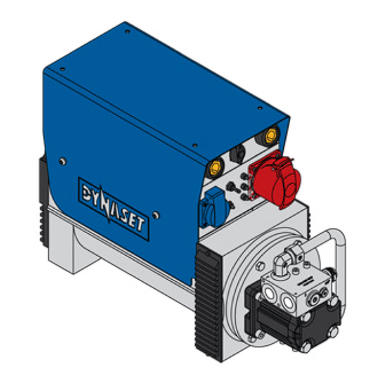
Page 9: Main Components Of Hwg
11. Welding current range selector 6. Electric sockets 12. Welding/Generator switch Place may vary Optional Welding controls of each model are described in chapter 5. Dynaset Oy | Menotie 3, 33470 Ylöjärvi | puh. 03 3488 200 | info@dynaset.com | www.dynaset.com... -
Page 10: Ip (Ingress Protection) Classification
HWG hydraulic generators are IP classified according to the IEC standard 60529 for the degrees of protection of electrical equipment. The protection class of standard HWG 180/220/300/400 hydraulic generators complies with the specifications IP23. Dynaset Oy | Menotie 3, 33470 Ylöjärvi | puh. 03 3488 200 | info@dynaset.com | www.dynaset.com... -
Page 11: Voltage And Frequency
The pictures are based on information on the internet page: http://www. worldstandards.eu/electricity/plugs-and-sockets. Picture 5: Single phase voltage and frequency world map Dynaset Oy | Menotie 3, 33470 Ylöjärvi | puh. 03 3488 200 | info@dynaset.com | www.dynaset.com... -
Page 12: Hydraulic Equipment
The product identification key describes which options are include in the HWG hydraulic generator’s structure. Drain line (L) An additional drain line can be installed if the pressure in tank line is too high. Dynaset Oy | Menotie 3, 33470 Ylöjärvi | puh. 03 3488 200 | info@dynaset.com | www.dynaset.com... -
Page 13: Electric Equipment
RCD is to be tested monthly. READ CHAPTER ”6.4. Test safety devices” for more information. Dynaset Oy | Menotie 3, 33470 Ylöjärvi | puh. 03 3488 200 | info@dynaset.com | www.dynaset.com... -
Page 14: Single Phase Socket Plug Type
The pictures are from: http://www.worldstandards.eu/electricity/plugs-and- sockets. NOTE! Ungrounded plugs and sockets A,C and I are unavailable. Picture 7: Single phase sockets and plugs Dynaset Oy | Menotie 3, 33470 Ylöjärvi | puh. 03 3488 200 | info@dynaset.com | www.dynaset.com... -
Page 15: Picture 8: Single Phase Plug And Socket World Map
Note that the map is for general use only and the plug & socket types might vary from it. Picture 8: Single phase plug and socket world map Dynaset Oy | Menotie 3, 33470 Ylöjärvi | puh. 03 3488 200 | info@dynaset.com | www.dynaset.com... -
Page 16: Three Phase Socket Plug Type
Number of poles current class position 380-415 V 16 A 3p + n + e 380-415 V 16 A 3p + n + e Dynaset Oy | Menotie 3, 33470 Ylöjärvi | puh. 03 3488 200 | info@dynaset.com | www.dynaset.com... -
Page 17: Safety
The hydraulic system can be pressurized up to 420 bar. WARNING HIGH PRESSURE OIL! Can cause severe injuries. Always wear appropriate clothing and safety equipment. Dynaset Oy | Menotie 3, 33470 Ylöjärvi | puh. 03 3488 200 | info@dynaset.com | www.dynaset.com... -
Page 18: Safety Equipment
Do not exceed the maximum load. WARNING RISK OF BURNS! The unit parts and oil can be hotter than 80°C! Wear personal safety equipment! Dynaset Oy | Menotie 3, 33470 Ylöjärvi | puh. 03 3488 200 | info@dynaset.com | www.dynaset.com... - Page 19 WARNING RISK OF FIRE. Welding sparks can cause explosion or re. Keep ammable material away from welding area. Do not weld in closed containers. Dynaset Oy | Menotie 3, 33470 Ylöjärvi | puh. 03 3488 200 | info@dynaset.com | www.dynaset.com...
-
Page 20: Maintenance Safety
ATTENTION! Before beginning any maintenance or repair, ensure that the system is switched off. Make sure that the system can not start accidentally. Dynaset Oy | Menotie 3, 33470 Ylöjärvi | puh. 03 3488 200 | info@dynaset.com | www.dynaset.com... -
Page 21: Warning Labels
Clean surface with solvent detergent before attaching labels. USE EAR PROTECTION READ OPERATING BEWARE OF HOT AND SAFETY GOGGLES. INSTRUCTIONS. SURFACE. Dynaset Oy | Menotie 3, 33470 Ylöjärvi | puh. 03 3488 200 | info@dynaset.com | www.dynaset.com... - Page 22 HYDRAULIC WELDING GENERATORS SAFETY Dynaset Oy | Menotie 3, 33470 Ylöjärvi | puh. 03 3488 200 | info@dynaset.com | www.dynaset.com...
-
Page 23: Operating Principles
DYNASET hydraulic welding generators have also an anti-stick function that activates when the electrode gets stuck during welding. Anti-stick function then cuts the welding current and keeps the electrode from being damaged. Dynaset Oy | Menotie 3, 33470 Ylöjärvi | puh. 03 3488 200 | info@dynaset.com | www.dynaset.com... -
Page 24: Auxiliary Voltage Control
Q is kept constant. The best power to pressure ratio is achieved when the pressure is at nominal level, little under the maximum value. READ CHAPTER ”10. TECHNICAL SPECIFICATIONS” for more information. Dynaset Oy | Menotie 3, 33470 Ylöjärvi | puh. 03 3488 200 | info@dynaset.com | www.dynaset.com... -
Page 25: Picture 12: Pressure/Power Chart
HYDRAULIC WELDING GENERATORS OPERATING PRINCIPLES Picture 12: Pressure/Power chart Dynaset Oy | Menotie 3, 33470 Ylöjärvi | puh. 03 3488 200 | info@dynaset.com | www.dynaset.com... - Page 26 HYDRAULIC WELDING GENERATORS OPERATING PRINCIPLES Dynaset Oy | Menotie 3, 33470 Ylöjärvi | puh. 03 3488 200 | info@dynaset.com | www.dynaset.com...
-
Page 27: Installation
If you are unsure of the hydraulic system, please contact the manufacturer of your base machine. Next three paragraphs describe the hydraulic systems in more detail. Dynaset Oy | Menotie 3, 33470 Ylöjärvi | puh. 03 3488 200 | info@dynaset.com | www.dynaset.com... -
Page 28: Picture 13: Open Centre Hydraulic System With Load Sensing Variable Displacement Pump
In variable- displacement pump, the flow rate and output pressure adjusts automatically based on the load of the hydraulic system. Dynaset Oy | Menotie 3, 33470 Ylöjärvi | puh. 03 3488 200 | info@dynaset.com | www.dynaset.com... -
Page 29: Picture 14: Connection Figure For Open Centre Hydraulic System With Load Sensing Variable Displacement Pump
5. Oil cooler 2.1. DYNASET PC-SAE pressure compensator 6. Oil filter 2.2. DYNASET LSV Load 7. Oil tank Sensing valve 3. Base machine’s variable displacement pump Dynaset Oy | Menotie 3, 33470 Ylöjärvi | puh. 03 3488 200 | info@dynaset.com | www.dynaset.com... -
Page 30: Picture 15: Closed Centre Hydraulic System With Load Sensing Variable Displacement Pump
The pump can rest when the oil is not required to operate a function. In variable-displacement pump, the flow rate and output pressure adjusts automatically based on the load of the hydraulic system. Dynaset Oy | Menotie 3, 33470 Ylöjärvi | puh. 03 3488 200 | info@dynaset.com | www.dynaset.com... -
Page 31: Picture 16: Connection Figure For Closed Centre Hydraulic System With Load Sensing Variable Displacement Pump
2. DYNASET LSV Load Sensing valve 6. Oil cooler 3. DYNASET Shuttle valve 7. Oil filter 4. Base machine’s variable 8. Oil tank displacement pump Dynaset Oy | Menotie 3, 33470 Ylöjärvi | puh. 03 3488 200 | info@dynaset.com | www.dynaset.com... -
Page 32: Picture 17: Hydraulic System With Constant Displacement Pump
Every stroke of the hydraulic motor moves the same amount of oil. The output flow is function of the motor’s rpm and pump’s displacement. Dynaset Oy | Menotie 3, 33470 Ylöjärvi | puh. 03 3488 200 | info@dynaset.com | www.dynaset.com... -
Page 33: Picture 18: Connection Figure For Hydraulic System With Fixed Displacement Pump
5. Oil cooler 2.1. DYNASET PC-SAE pressure compensator 6. Oil filter 2.2. DYNASET LSV Load 7. Oil tank Sensing valve 3. Base machine’s fixed displacement pump Dynaset Oy | Menotie 3, 33470 Ylöjärvi | puh. 03 3488 200 | info@dynaset.com | www.dynaset.com... -
Page 34: Dynaset Valves
DYNASET PV-SAE PRIORITY VALVE Picture 20: PV-SAE Priority valve DYNASET PV- SAE priority valve enables the installations of the DYNASET products into any hydraulic system. Dynaset Oy | Menotie 3, 33470 Ylöjärvi | puh. 03 3488 200 | info@dynaset.com | www.dynaset.com... -
Page 35: Installing Dynaset Hydraulic Product
Pressure (P) and return (T) lines of a hydraulic system are connected to the DYNASET units corresponding hydraulic ports. Picture 22: Installing hydraulic hoses Dynaset Oy | Menotie 3, 33470 Ylöjärvi | puh. 03 3488 200 | info@dynaset.com | www.dynaset.com... -
Page 36: Picture 23: Hydraulic Flow At Least Minimal
Generally DYNASET’s return line(T) is to be connected directly to the return line of a hydraulic system. Picture 25: Return line (T) pressure must be under 5 bars. Dynaset Oy | Menotie 3, 33470 Ylöjärvi | puh. 03 3488 200 | info@dynaset.com | www.dynaset.com... -
Page 37: Hydraulic Fluids
B. Minimum 50 mm NOTE! Sufficient venting is important. HWGs components heat up during the use. Maintain the generator accordingly and keep the vents open and clean. Dynaset Oy | Menotie 3, 33470 Ylöjärvi | puh. 03 3488 200 | info@dynaset.com | www.dynaset.com... -
Page 38: Grounding
Ground the HWG hydraulic welding generator from the marked grounding spot in generators frame. The grounding spot varies between different generator models. Picture 27: Grounding the HWG hydraulic welding generator Dynaset Oy | Menotie 3, 33470 Ylöjärvi | puh. 03 3488 200 | info@dynaset.com | www.dynaset.com... -
Page 39: Ip Code Requirements
Hz-position and check the frequency between a phase and ground. Frequency value should be 50 Hz ± 5%. Picture 29: Measuring frequency Dynaset Oy | Menotie 3, 33470 Ylöjärvi | puh. 03 3488 200 | info@dynaset.com | www.dynaset.com... - Page 40 NOTE! DYNASET HWG hydraulic welding generators are tested and adjusted at factory! Do not adjust frequency without real need. Dynaset Oy | Menotie 3, 33470 Ylöjärvi | puh. 03 3488 200 | info@dynaset.com | www.dynaset.com...
-
Page 41: Operation
(only in HWG 300)) D. Arc force potentiometer (only in HWG 300) E. Voltage ON - indicator light F. Welding overload warning (only in HWG 300) Dynaset Oy | Menotie 3, 33470 Ylöjärvi | puh. 03 3488 200 | info@dynaset.com | www.dynaset.com... -
Page 42: Starting Hwg
Both electrode-positive and electrode negative welding methods are possible with DYNASET HWG welding generators. To enable electro- negative welding connect the welding cables invertly to the terminals A. Dynaset Oy | Menotie 3, 33470 Ylöjärvi | puh. 03 3488 200 | info@dynaset.com | www.dynaset.com... -
Page 43: Selecting Welding Current With Hwg 180/220/400
Picture 32: Welding ATTENTION! Always remember to use proper safety equipment such as a welding mask, dry insulating gloves and suitable outfit. Dynaset Oy | Menotie 3, 33470 Ylöjärvi | puh. 03 3488 200 | info@dynaset.com | www.dynaset.com... -
Page 44: Connecting A Load To Generator
Picture 33: HWG with connected load NOTE! It is recommended to use UPS(uninterruptable power source) with electrical equipment such as computers to protect them from power surges and spikes. Dynaset Oy | Menotie 3, 33470 Ylöjärvi | puh. 03 3488 200 | info@dynaset.com | www.dynaset.com... -
Page 45: Stopping The Hwg
Depending on the batterys age and condition you may have to repeat the above several times. After engine starts disconnect cables from battery immediately. Dynaset Oy | Menotie 3, 33470 Ylöjärvi | puh. 03 3488 200 | info@dynaset.com | www.dynaset.com... -
Page 46: Remote Control
If the HWG hydraulic welding generator overheats or overloads, it shuts off automatically. The unit will switch itself back on operational after a few minutes. Dynaset Oy | Menotie 3, 33470 Ylöjärvi | puh. 03 3488 200 | info@dynaset.com | www.dynaset.com... -
Page 47: Ambient Temperature
POWER TAKEOFF, P % 100% t,ºC -20 -10 70 75 AMBIENT TEMPERATURE Picture 35: Power take off in higher temperatures Dynaset Oy | Menotie 3, 33470 Ylöjärvi | puh. 03 3488 200 | info@dynaset.com | www.dynaset.com... - Page 48 HYDRAULIC WELDING GENERATORS OPERATION Dynaset Oy | Menotie 3, 33470 Ylöjärvi | puh. 03 3488 200 | info@dynaset.com | www.dynaset.com...
-
Page 49: Maintenance
ISO VG 46S 70 °C ISO VG 68S 80 °C NOTE! Recommended oil viscosity is between 10 to 35 cSt when operating at normal operating temperature. Dynaset Oy | Menotie 3, 33470 Ylöjärvi | puh. 03 3488 200 | info@dynaset.com | www.dynaset.com... -
Page 50: Cleaning Hwg Hydraulic Welding Generator
Check your equipment after every work shift. Depending on the operational environment, clean the HG hydraulic generator as frequently as necessary to keep it in perfect working condition. Picture 36: Cleaning HWG Dynaset Oy | Menotie 3, 33470 Ylöjärvi | puh. 03 3488 200 | info@dynaset.com | www.dynaset.com... -
Page 51: Test Safety Devices
When the test button is pressed the switch must release immediately. Use of the HWG hydraulic welding generator with faulty safety equipment is forbidden until they are replaced. Dynaset Oy | Menotie 3, 33470 Ylöjärvi | puh. 03 3488 200 | info@dynaset.com | www.dynaset.com... -
Page 52: Adjusting Output Frequency
When measuring output frequency, act in compliance with the laws, regulations and recommendations issued by local electricity, work safety authorities and universal multimeter manufacturer. Dynaset Oy | Menotie 3, 33470 Ylöjärvi | puh. 03 3488 200 | info@dynaset.com | www.dynaset.com... -
Page 53: Picture 38: Adjusting The Frequency
B more. Do not make more than quarter revolution turns at the time! Dynaset Oy | Menotie 3, 33470 Ylöjärvi | puh. 03 3488 200 | info@dynaset.com | www.dynaset.com... -
Page 54: Picture 39: Cartridge Tuning Without Installation Valve 1
4. Then turn the screw B counter-clockwise for a another quarter of revolution. 5. Lock the setting with the locknut A tightening it to 10 Nm. Dynaset Oy | Menotie 3, 33470 Ylöjärvi | puh. 03 3488 200 | info@dynaset.com | www.dynaset.com... -
Page 55: Picture 40: Cartridge Tuning Without Installation Valve 2-5
HYDRAULIC WELDING GENERATORS MAINTENANCE Picture 40: Cartridge tuning without installation valve 2-5 Dynaset Oy | Menotie 3, 33470 Ylöjärvi | puh. 03 3488 200 | info@dynaset.com | www.dynaset.com... -
Page 56: Troubleshooting
NOT BE STRUCK OR IS Verify the winding resistance with DIFFICULT parameters shown in technical spe- Winding failure. cification and replace stator/rotor if damaged. Dynaset Oy | Menotie 3, 33470 Ylöjärvi | puh. 03 3488 200 | info@dynaset.com | www.dynaset.com... - Page 57 Check all internal contacts and wirings LOW OUTPUT VOLTAGE Poor contact in electric of the generator. Check and clean AT NO LOAD system. brushes and slip ring. Dynaset Oy | Menotie 3, 33470 Ylöjärvi | puh. 03 3488 200 | info@dynaset.com | www.dynaset.com...
- Page 58 Check whether the hydraulic fluid flow and pressure are not excessive. Adjust when necessary. Check the hydraulic motor for pos- sible leakage. Replace the motor if necessary. Dynaset Oy | Menotie 3, 33470 Ylöjärvi | puh. 03 3488 200 | info@dynaset.com | www.dynaset.com...
-
Page 59: Manufacturer's Limited Warranty
DYNASET OY or to other location authored by DYNASET OY. Shipment documents must contain: Purchaser’s name and contact information Receipt of original purchase WRN code Problem description Dynaset Oy | Menotie 3, 33470 Ylöjärvi | puh. 03 3488 200 | info@dynaset.com | www.dynaset.com... - Page 60 • Product that is used in exceptional conditions, considered to cause excessive wear and tear. • Faults caused by nature phenomenon’s like flood, thunder, etc. © DYNASET OY, all rights reserved Dynaset Oy | Menotie 3, 33470 Ylöjärvi | puh. 03 3488 200 | info@dynaset.com | www.dynaset.com...
-
Page 61: Product Disposal
NOTE! Always act according to the waste legislation, regulations and recommendations in waste disposal and waste recycling issued by your local authorities. Dynaset Oy | Menotie 3, 33470 Ylöjärvi | puh. 03 3488 200 | info@dynaset.com | www.dynaset.com... - Page 62 HYDRAULIC WELDING GENERATORS PRODUCT DISPOSAL Dynaset Oy | Menotie 3, 33470 Ylöjärvi | puh. 03 3488 200 | info@dynaset.com | www.dynaset.com...
-
Page 63: Declaration Of Conformity
If the device has been modified by someone other than the manufacturer or without the manufacturer’s permission, this declaration is not valid. Timo Nieminen R&D Manager Ylöjärvi, Suomi, 20.4.2016 Dynaset Oy | Menotie 3, 33470 Ylöjärvi | puh. 03 3488 200 | info@dynaset.com | www.dynaset.com... - Page 64 HYDRAULIC WELDING GENERATORS DECLARATION OF CONFORMITY Dynaset Oy | Menotie 3, 33470 Ylöjärvi | puh. 03 3488 200 | info@dynaset.com | www.dynaset.com...
-
Page 65: Technical Specifications
* Nominall current (1~phase / 3~phase) /phase must not exceed maximum load. ** Ref. to hydraulic fluids in chapter 6.2 *** Minimum cooling capacity for HG hydraulic generator on the base machine. Dynaset Oy | Menotie 3, 33470 Ylöjärvi | puh. 03 3488 200 | info@dynaset.com | www.dynaset.com... - Page 66 HYDRAULIC WELDING GENERATORS TECHNICAL SPECIFICATIONS Dynaset Oy | Menotie 3, 33470 Ylöjärvi | puh. 03 3488 200 | info@dynaset.com | www.dynaset.com...
- Page 67 © DYNASET OY, med enerett.
- Page 68 Menotie 3 FI-33470 Ylöjärvi, Finland tlf: +358 3 3488 200 info@DYNASET.com ELECTRICITY MAGNET POWER HG Hydraulic Generator HMG PRO Hydraulic Magnet Generator HGV POWER BOX Variable Hydraulic Generator System MAG Lift Magnet HGV Variable Hydraulic Generator System HMAG PRO Hydraulic Magnet...
Need help?
Do you have a question about the HWG 220/6K-49 and is the answer not in the manual?
Questions and answers