
Summary of Contents for Rioned UNICOM
- Page 1 USER’S MANUAL UNICOM RIONED P.O. Box 5070 5004 EB Tilburg The Netherlands Telephone: +31 13 5479100 Internet: www.rioned.com e-mail info@rioned.com...
- Page 2 RIONED. This restriction also holds for the corresponding drawings and diagrams. RIONED has the right to change parts at any time without any prior or direct warning to the client. Also, the contents of this manual can be changed without any prior warning.
- Page 3 Foreword. This user’s manual is a manual for the professional user. This user’s manual has the purpose to control the machine in a safety manner and must be saved with the machine. The photos and drawings help you understand the text easier. First the user’s manual gives you an overview of the most important safety aspects.
- Page 4 12/12...
-
Page 5: Table Of Contents
TABLE OF CONTENTS INTRODUCTION ....................... 7 Use..........................7 SECURITY........................... 9 Instruction indications in this manual................9 Description security measures..................9 Personnel protection outfit ..................9 Warnings........................9 Personnel qualification and education............... 10 Danger that can occur if the security regulations aren’t observed ......10 Working safely ...................... - Page 6 OPTIONS ........................... 41 Hour counter......................41 Pulsator system......................41 Working lamp......................41 Anti-freeze with anti freeze tank ................41 Radio remote control type Riomote ................42 Hose guide ......................... 43 Run dry protection..................... 44 MAINTENANCE....................... 45 Daily maintenance ..................... 45 Weekly maintenance ....................
-
Page 7: Introduction
INTRODUCTION RIONED thanks you for your purchase of the RIONED drain and sewer-clearing machine. We rec- ommend that you read this manual thoroughly and see that the machine is handled and maintained in the proper manner. If your machine should give trouble and need servicing, when you want to order parts, or if you have any questions, contact your RIONED dealer. - Page 8 12/12...
-
Page 9: Security
SECURITY Be responsible for other people when you are working with this machine. This manual contains instructions for fundamental conditions that must be followed by use and maintenance of this machine. That is why it is necessary that authorised and qualified personnel must read the user's manual and the user’s manual must always be available with the machine. -
Page 10: Personnel Qualification And Education
Before starting the machine again, you must follow the instructions correctly. 2.10 Making Changes to the machine are only permitted if Rioned has given written authorisation. The use of changes and original spare parts and accessories are for the safety necessary. Rioned is not responsible for inju- fabricate spare ries or damages if other spare parts are used. - Page 11 vice is positioned correctly, properly controlled, and regularly maintained, a warranty will be given according to the general conditions of delivery. However, should it arise that the control and main- tenance procedures are not diligently followed, the warranty will become invalid. 12/12...
- Page 12 12/12...
-
Page 13: Technical Specifications
TECHNICAL SPECIFICATIONS 3.1 General Year of constructions (month/year) 12/12 Capacity vacuum tank 1000 l Capacity water tank 500 l Dimensions see chapter 12.6 Dimensions page: 62 Length HP hose 80 m Diameter HP hose ½” (NW13) Length supply hose 50 m Diameter supply hose 5/8”... - Page 14 Type Kubota V1505 Number of cylinder Bore x stroke (d x l) 78 x 78,4 mm (3.07 x 3.09 in.) Power (P) 26,1 kW at 3000 min-1 DIN 70020 Fuel Diesel Cooling Water cooled Weight (m) 110 kg Battery (U,I) 12 V, 45 A Starter 12 V x 1,2 kW...
-
Page 15: Pump
3.3 Pump Description (symbol) Technical unit Type Speck P41 Number of plungers Number of valves Number of revolutions (n) 1200 min Maximum pressure (p) See type plate on frame Maximum output (V/t) See type plate on frame GX 80W90 Quantity (V) Weight (m) 30 kg Maximum water temperature (t,T) - Page 16 12/12...
-
Page 17: Construction And Functioning
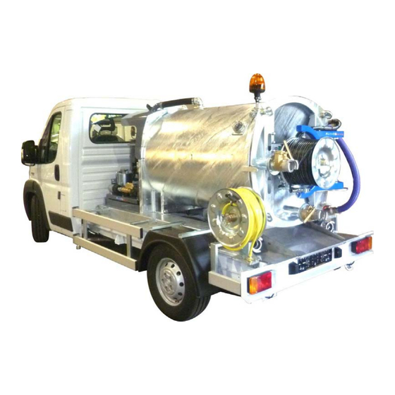
CONSTRUCTION AND FUNCTIONING The suction unit contains the following main parts: High-pressure pump Charger (radio remote control) Reel with suction hose Suction pipe Water filter Suction hose storage reel Oil tank hydraulic system Supply valve Antifreeze Control box Antifreeze tank Dirt water tank (Vacuum tank) Not included or visible Sight glass / level indicator... - Page 18 12/12...
- Page 19 12/12...
- Page 20 12/12...
- Page 21 12/12...
- Page 22 12/12...
-
Page 23: Control
CONTROL If you control, maintain or inspect the machine, you must have the right qualifications for this job. If you do not have the necessarily knowledge, you may not use the machine. Further, you must convince yourself that you understand this manual thoroughly. -
Page 24: Hydraulic Reel Control
Unclogging of a drain: jet nozzle. 5.2 Hydraulic reel By means of pushing the control lever (11) upwards or downwards the high-pressure control hose can be unrolled or rolled up. Due to the proportional functioning of this valve you can also control the speed of the reel. -
Page 25: Starting The Engine
5.3 Starting the engine Emergency stop: The machine is equipped with an emergency stop. By operating this stop the machine will stop immediately. Do not use the button for normal stopping. Only use is when dangerous situations occur. After use, turn the emergency stop in order to be able to start up again. - Page 26 Via control box (Diesel engine): Put the ignition key into the keyhole Choose “hand control” Control lights Oil pressure and charging lightens. If not, then Troubleshooting. Wait 5 seconds! Turn start/stop switch to the right and release it. Glow spiral lightens , goes off and then the engine starts.
- Page 27 Warm up the engine for 2 or 3 minutes. If the choke knob was pulled to the CLOSED position to start the engine, gradually push it to the OPEN position as the engine warms For a more detailed description see enclosed engine book or Internet site. (http://engines.honda.com/pdf/manuals/00X37Z6L6010.pdf) Starting on control box: Insert the key into the ignition (A).
-
Page 28: Unclogging A Drain
5.4 Unclogging a Screw a suitable nozzle onto the high-pressure hose (10). drain Put the hose through the hose guide (14) for safety manners (option). Unwind the hose a little. Put the nozzle into the drain that is to be cleaned. Screw the pressure regulator (16) fully open (right). - Page 29 may cause severe injuries! Stop spraying: • Press button (Throttle close) or press button “RPM-” (sender). • Press button (HP pump off) or press button “HP off” (sender). Treat the high-pressure hose carefully: • Always clean it after use. • Ensure that no sharp objects are near the hose.
-
Page 30: Cleaning A Wall, Terrace Or Floor
5.5 Cleaning a wall, terrace or floor. Caution! Before using a spray gun, you must always set the pressure below the maximum (±the half of the maximum pressure). You must do this before you start the machine. If the machine is running, the pressure can be increased by turning the control wheel to his working pressure. -
Page 31: Stop Working
5.6 Stop working Press button (Throttle close) or “RPM-” on the radio remote control. Press button (HP pump off) or “HP off” on the radio remote control. Close the HP valve. 5.7 Spray gun Instead of the spray lance gun, you can also mount a NW5 hose with small nozzle onto the spray with NW 5 hose gun. -
Page 32: Additional Preparations When Preparing For Use
5.9 Additional Turn on the machine and let the high-pressure pump drain all antifreeze into the anti- preparations when freeze tank. The antifreeze can be reused. preparing for use: Ensure that no water is mixed with the antifreeze. If too much water gets into the antifreeze, it is not suitable for re-use. -
Page 33: Using The Vacuum Device
USING THE VACUUM DEVICE 6.1 Use Use the vacuum system only for cleaning sewers and tanks (see chapter 1 Introduction page: 7). 6.2 Before use: Close the suction valve (9) and press valve (8). Clean the syphon (21). Clean the float ball protection in the vacuum tank (dirt and functioning) always before use. -
Page 34: Empty The Dirt Water Tank
Check the oil dropper ( ) on the vacuum pump. The dropper must give 7-10 drops/ min. (only MEC). Open the suction valve (9) or “Valve open” at the remote control. The vacuum tank gets filled. Remark! The vacuum pump is protected against overheating and will, incase of overheating, be shut off automatically. - Page 35 connection in the vacuum tank in front of the valve is blocked with sand or stones. Press button (Throttle close) or “RPM-” on the radio remote control Press button at the control box or button “VAC off” on the transmitter. Stop the engine, press button or “Stop”...
- Page 36 12/12...
-
Page 37: Stickers And Symbols
STICKERS AND SYMBOLS Engine start/stop. Engine glow. Signal lamp “Charging” (Burns if there is no charge to the battery). Signal lamp “Oil pressure” (Burns if there is not enough oil in the engine). 12 V accessories. Vacuum pump ON Vacuum pump OFF Run dry protection 12/12... - Page 38 Throttle open Throttle close HP ON (Start spraying) HP OFF (Stop spraying) “Hand” or “Radio remote” control Signal lamp “Radio remote control” on Back plate “Emergency stop” 12/12...
-
Page 39: Pressure Gauge
7.1 Pressure gauge Maximum allowed pressure Danger zone Working area 7.2 Pressure Less pressure More pressure regulator 7.3 Valve control Open and close valve: 12/12... -
Page 40: Security Sticker
7.4 Security sticker 12/12... -
Page 41: Options
OPTIONS 8.1 Hour counter This machine is equipped with an hour counter. The hour counter indicates the number of working hours that the machine has worked. 8.2 Pulsator system Purpose: With less water use, quicker to the stoppage. Construction: The high-pressure pump has three cylinders. By normal use the three cylinders follows each other continuously. -
Page 42: Radio Remote Control Type Riomote
Let the high-pressure pump remove all the water, which is still in the high-pressure hose and pump. Close the high-pressure valve or push button, when anti freeze flows out of the HP hose (watch the colour of the water). Connect the HP-hose (with special connection) to the supply hose. Open the supply valve. -
Page 43: Hose Guide
If the indication on the transmitter starts burning it´s indicates that the battery must be changed with a new fully loaded battery. If the battery is not changed the transmitter switches off in a short time. Reload empty batteries. Functions: Start the engine (only 7 channel version) Stop the engine (only 7 channel version) High-pressure pump on (start spraying) -
Page 44: Run Dry Protection
8.7 Run dry protec- The run-dry protection has the purpose to protect the high-pressure pump. tion Functioning: If the water level in the tank is too low, the run-dry protection activates. Cancelling: Fill the water tank. (Supply hose, Fill opening, Supply pipe...) 12/12... -
Page 45: Maintenance
MAINTENANCE Attention! Always stop the engine first and depressurize the system before serving or repairing the machine. To depressurize the system, you open the HP valve. If the spray lance gun is attached you must also pull the trigger. To depressurize the vacuum tank, you open the suction valve. 9.1 Daily mainte- Oil level nance... -
Page 46: Vacuum Filter
• Cleaning the high-pressure control: When the high-pressure valve has been closed, the pressure gauge should not indicate any pressure. Similarly, if the spray gun is connected and closed, the pressure gauge should not indicate any pressure. If the pressure gauge does indicate a pressure, this im- plies a leakage in the system or that the one-way valve may be dirty or damaged. -
Page 47: Hydraulic System
Important! You have to renew the hydraulic oil at least ones a year! Only use oil HESTIA 46. Order number Rioned 71-003-500-046 Check, every time before use, if the level of the oil is sufficient. Proceed as follows: Stop the machine. -
Page 48: Cleaning The Float Ball (Siphon)
9.10 Extensive peri- Have the high-pressure machine checked and maintained from time to time by the technical service odical maintenance of Rioned. In this way, long life and quality will be guaranteed. 9.11 Maintenance Interval scheme... -
Page 49: Troubleshooting
TROUBLESHOOTING Failure Reason Solution Engine does not start or stops abruptly. Machine has run out of fuel Add fuel Main or secondary fuse blown Replace the defect fuse and restart engine. If problem repeats, contact your dealer Battery voltage too low. Load or replace. - Page 50 Failure Reason Solution No suction of the vacuum pump Switch doesn’t supply current to magnet coupling Contact your dealer Magnet coupling doesn’t work Contact your dealer Vacuum valve or press valve in open position Close the valve Lever vacuum valve suction/pressure in wrong Put the lever in the right position position Clamp bolts not well-fastened...
-
Page 51: Exploded Views And Part Lists
EXPLODED VIEWS AND PART LISTS 12/12... -
Page 52: Siphon
An Affiliate of Spartan Tool L.L.C. Tel.: 013-5479100 Fax: 013-5479104 Maten in mm Tek.no.: Deze tekening is eigendom van Rior B.V. / Rioned en mag zonder haar toestemming niet vermenigvuldigd, 60456060065 noch aan derden ter inzage gegeven worden. WWW.RIONED.COM File: C:\VaultLibraries\Bibliotheek\_Parts\60 Kamlock koppelingen\60456060065.iam... -
Page 53: Exploded View Pump P41(48L-180B)
11.2 Exploded view Pump P41(48L-180B). 12/12... -
Page 54: Exploded View Pump P45(75L-150B)
11.3 Exploded view Pump P45(75L-150B). 12/12... -
Page 55: Pressure Regulator Ulh 262
11.4 Pressure regulator ULH 262 Item No. Qty Order number Factory No. Description 1 67-262-101-001 01-0630 Casing 1 67-262-101-002 07-2788 Guide Plug 1 67-262-101-102 06-1131 Guide ring 1 67-262-101-003 06-0255 O-Ring 1 67-262-101-005 11-0477 Piston Rod 1 67-262-101-006 06-1129 O-Ring for 5 1 67-262-101-007 00-6113 Support Ring for 6... - Page 56 12/12...
-
Page 57: Appendix
Of Centaurusweg 45, Tilburg, The Netherlands, Conformity For Machinery Herewith declares that: High pressure device RIONED Suction / High-pressure unit, Machine number: 10005002013128 • is in compliance with the Machinery Directive (2006/42/EC); • is in conformity with the provisions of the following other EEC directives: 2004/108/E •... -
Page 58: Sales Managers
Managers D.Maas / H. de Laat Centaurusweg 45 5015 TC Tilburg Tel.: +31 13-547 91 00 Fax: +31 13-547 91 04 REPAIR Rioned Centaurusweg 45 5015 TC Tilburg Netherlands Tel.: +31 13-547 91 50 Fax: +31 13-547 91 04 12/12... -
Page 59: Electric Scheme
12.3 Electric scheme 12/12... -
Page 60: Electric Scheme Riomote
12.4 Electric scheme Riomote Not necessary 12/12... -
Page 61: Hydraulic Oil
Important! 12.5 Hydraulic oil You have to renew the environment friendly hydraulic oil ones a year. Description Hydraulic oil is an environment friendly oil based on vegetable oil. By use of natural vegetable oil, the hydraulic oil is neutral for the environment and is biologically decomposable. When spilling some oil, the ground as well the around water are less damaged by contamination. -
Page 62: Dimensions
12.6 Dimensions 12/12... -
Page 63: Index
......9 chemicals ........7 cleaning ........45 copyright ........2 knowledge ........23 reason ........... 49 responsible ........9 rioned ......2 danger zone ........47 run dry protection ......37 decalcify pressure valves .....48 rust ..........47 decalcify suction valves ....48 lightning ........7 dipsticks ........23... - Page 64 ventilation ........7 traffic ..........29 year of constructions ....13 transmitter ........50 warning signal ......50 warranty ........11 wastage ........61 weather conditions ......7 vegetable oil .........61 12/12...
Need help?
Do you have a question about the UNICOM and is the answer not in the manual?
Questions and answers