Advertisement
Advertisement
Table of Contents

Summary of Contents for Unitor UPC 85 ML
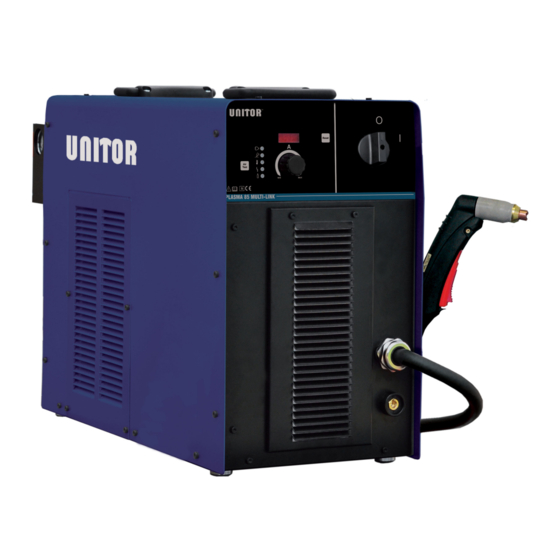
- Page 1 Instruction manual UPC 85 ML Air Plasma Cutter...
- Page 2 Revision summary Rev. No. Version Date issued 6938800000 April 24, 2018 6938800000 September 23, 2019...
-
Page 3: Table Of Contents
CONTENTS 1.Safety instructions 2.Technical data 3.Installation 4.Operating instructions 5.Torch parts 6.Maintenance 7.Trouble shooting 8.Cutting/thickness characteristics 9.Wiring diagram 10.Parts list DELIVERY UPC-85 ML Air Plasma Cutter 404185 delivery consist of: Machine supply complete with 3,5m primary cable 3+G x 4mm Torch with 6m cable (connected directly to the machine) Return clamp with 6m cable with Dix25 Initial supply consumables kit of 2 x Electrode, 2 x Tip Cutting, 1 x Cartridge, 1 x Shield Cup Air regulator with filter and water separator mounted on the machine... -
Page 4: Safety Instructions
1 SAFETY INSTRUCTIONS ELECTRIC SHOCK CAN KILL - Disconnect the power supply before working on the plasma machine. - Do not work with deteriorated cable sheaths. - Do not touch bare electrical parts. - Ensure that all the panels covering the plasma machine are firmly secured in place when the machine is connected to the mains supply. - Page 5 PREVENTION OF BURNS To protect your eyes and skin from burns and ultraviolet rays: - wear dark glasses. Wear suitable clothing, gloves and footwear. - use masks with closed sides, having lenses and protective glass according to standards (degree of protection DIN 10).
-
Page 6: Technical Data
2 TECHNICAL DATA Power supply 230V ±10% 1~50/60 Hz 400-440V ±15% 3~50/60 Hz Mains fuse minimum (Slow 230V 1P: 25A 400-440V 3P: 20A blow) Maximum power 230V 1F: 7,45 KVA 400-440V 3F: 12,10 KVA Process power 88V – 20A 88V – 20A 104V –... -
Page 7: Installation
3 INSTALLATION WARNING: This Class A equipment is not intended for use in residential locations where the electrical power is provided by the public low-voltage supply system. There may be potential difficulties in ensuring electromagnetic compatibility in those locations, due to conducted as well as radiated disturbances. This equipment is complying with IEC 61000-3-12 and It can be connected to a public and private low voltage system. -
Page 8: Operating Instructions
PNEUMATIC CIRCUIT CONNECTION: The machine uses compressed air for plasma cutting. Any cylinder of compressed air may therefore be used, or air from a compressor. The air must be free from polluting particles, such as oil or other contaminating agents. A pressure regulator is provided to ensure the correct air flow rate on the torch. KEY: 1–... - Page 9 FRONT PANEL DESCRIPTION Air presence LED Reset Protection alarm LED Air Test button Excess temperature LED Welding enabled LED Machine Live LED Cutting current regulation Cutting current display RESET button ON-OFF switch For the number reference below, refer to the Front Panel Description: 1.Turn the switch on the back panel to ON position.
- Page 10 START-UP The red led (2) is illuminated and the unit is now in STAND-BY. In order to perform plasma cutting operation, please follow the following steps: 2.Set the output current (7) to a suitable value for the thickness that is to be cut. For thin materials reduced output may be required to obtain a smooth and neat cut.
- Page 11 CUTTING TECHNIQUE For best performance and life expectancy, always use the correct and original parts for cutting torch. 1.Install the cutting tip and set the output current. 2.Hold the torch away from your body. 3.Slede the trigger release toward the back of the torch handle while simultaneously squeezing the trigger.
-
Page 12: Torch Parts
5 TORCH PARTS FOR INPUT VOLTAGE 400-440V 3F / 230V 1F. DESCRIPTION PRODUCT NUMBER COMMENTS Tip Drag Cutting 30A 310336 5 PCS Tip Cutting 85A 404181 5 PCS Tip Gouging 85A 404165 5 PCS Electrode 310334 5 PCS Shield Cup Body Maximum Life 404173 1 PCS Shield Cup Body... -
Page 13: Maintenance
6 MAINTENANCE This section describes basic maintenance procedures performable by operating personnel. No other adjustments or repairs are to be attempted by other than properly trained personnel. WARNING Disconnect primary power at the source before disassembling the power supply, torch, or torch leads. - Page 14 EVERY 3 TO 6 MONTHS AIR CLEAN (DRY AIR) THE INTERNAL PART OF THE PLASMA MACHINE Before cleaning the inside of the machine, it is obligatory to FIRST follow the WARNINGS described previously and to proceed as follows: 1- Remove the casing, slackening the side screws; 2- Remove all traces of dust from the internal parts of the machine by means of a jet of dry compressed air at a pressure no higher than 3 bar;...
-
Page 15: Troubleshooting
7 TROUBLESHOOTING The following lists the more common cutting faults and possible causes: 1. Insufficient penetration a. Cutting speed too fast b. Torch not at 90° c. Metal too thick d. Worn torch parts e. Cutting current too low f. NON- genuine manufacturer parts 2. - Page 16 RESET The Led (2) is ON, fix and the display shows the Amperage 1. The unit is simply in STAND-BY 2. Press the button RESET (7). See section STARTING UP TRIGGER ALLARM The Led (2) is ON fast blinking and display shows "TRI". 1.
- Page 17 PIP (PART IN PLACE) The Led (2) is ON , slow blinking and the display shows "PIP" 1. The consumables are not correctly mounted. 2. The unit is now blocked 3. Turn Off the unit and check consumables. See TROUBLESHOOTING MANUAL. OVERHEATING OF THE TORCH: After several minutes of cutting, the torch cap may become too hot to work.
- Page 18 DUTY CYCLE AND EXCESSIVE TEMPERATURE The Led indicator light 4 blink, and the display show HT (1,3,5,7) 1. This is indicating the unit has exceeded the Duty Cycle. The duty cycle is the percentage of use of the welding machine in 10 minutes which the operator must respect to avoid the power supply output blocking due to exceeding working temperature.
- Page 19 DISPOSAL OF ELECTRICAL AND ELECTRONIC EQUIPMENT Do not dispose of electrical equipment together with normal waste! In observance of European Directive 2012/19/EU on Waste Electrical and Electronic Equipment and its implementation in accordance with national law, electrical equipment that has reached the end of its life must be collected separately and returned to an environmentally compatible recycling facility.
-
Page 20: Cutting/Thickness Characteristics
8. CUTTING / THICKNESS CHARACTERISTICS Characteristics Thickness/ Cutting speed PLASMA 85 I2 = 85A 1torch SL100 I2 = 60A 1torch SL100 1500 1400 1300 1200 Fe C 1100 1000 9 10 11 12 13 14 15 16 17 18 19 20 21 22 23 24 25 26 27 28 29 30 31 32 33 34 35 36 37 38 39 40 41 42 Thickness (mm) Pressure = 4,8 bar Flow = 120 l/min... -
Page 21: Wiring Diagram
9. WIRING DIAGRAM... -
Page 22: Parts List
10. PARTS LIST... - Page 23 DESCRIPTION PRODUCT DESCRIPTION PRODUCT NUMBER NUMBER Handle 66103400 Right Output inductance 61132100 Cover 620671U0 Left Output inductance 61332300 Side grid 620673R0 Heatsink 63593000 Fan 120x120x38 64016000 Heatsink support 6206780U Fan support 6206790U Support for pcb 6206820U Pilot Arc Switch Cover 66107800 PCB Flyback 61282900...
-
Page 24: Declaration Of Conformity
The EMC Directive 2014/30/EU The RoHS Directive 2011/65/EU Type of equipment Plasma equipment Type of designation 601455000L – UPC 85 ML Brand name or trade mark UNITOR Manufacturer or his authorized representatives established within the EEA: Name, address, phone, website: STEL s.r.l...
Need help?
Do you have a question about the UPC 85 ML and is the answer not in the manual?
Questions and answers
Pawer light led no 2 is on not able to reset system blocked.
When LED No. 2 is ON and the Unitor UPC 85 ML system is blocked and cannot be reset, it may indicate one of the following alarm conditions:
1. Trigger Alarm: LED No. 2 is ON and blinking fast, and the display shows "TRI". This means the torch trigger was pressed or is broken when the unit was turned ON. The unit is blocked. To fix it, turn off the unit and check the torch.
2. PIP (Part In Place) Alarm: LED No. 2 is ON and blinking slowly, and the display shows "PIP". This means the consumables are not correctly mounted. The unit is blocked. To fix it, turn off the unit and check the consumables.
In both cases, the system is blocked for safety and requires checking and correcting the issue before restarting.
This answer is automatically generated