
Summary of Contents for MSG MS013 COM
- Page 1 2017.08.16 MSG MS013 COM ADAPTER FOR DIAGNOSTICS OF VOLTAGE REGULATORS USER MANUAL...
-
Page 3: Table Of Contents
6.1 Testing of the alternator assembly in the car ..................6.2 Testing of the voltage regulator separately from the alternator ........... 6.3 "PWM" mode (PWM generator) ......................... 6.4 "Oscillograph" mode............................ 7. SAFETY MEASURES WHEN WORKING WITH MS013 COM ................8. TEST CERTIFICATE ..............................APPENDIX 1 ................................. APPENDIX 2 ................................. -
Page 4: Description
User Manual - Adapter MSG MS013 COM 1. DESCRIPTION The Adapter MS013 COM is used for diagnostics of alternator voltage regulators. The device gives an opportunity to test voltage regulators both separately from the alternator and in assembly with the alternator with the test bench for diagnostics of alternators, or directly in the car. -
Page 5: Technical Characteristics
User Manual - Adapter MSG MS013 COM 2. TECHNICAL CHARACTERISTICS Diagonal 4,3” Color TFT-LCD display Resolution 480×272 pixels Supply voltage, V Battery 12, Supply type, V AC/DC power supply 5V/2А Power temperature, °С 0…50 Storage temperature, °С -10…+40 ≤75% under 0…+40 Relative humidity, °С... -
Page 6: Control Units
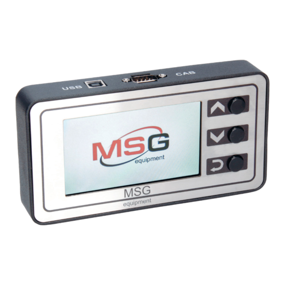
User Manual - Adapter MSG MS013 COM 3. CONTROL UNITS Fig. 1 – Adapter MS013 COM 3.1 Buttons "UP" button is used to select the needed option in the menu. In the РР testing mode increases the value of the needed electric pressure (except "L/D+" mode). -
Page 7: Connectors
User Manual - Adapter MSG MS013 COM 3.2 Connectors The device has D-SUB 9 pin connector to connect diagnostic cable (CAB) and USB connector to connect diagnostic cable for supply and software update. Two diagnostic cables are also included in the equipment set: Fig. - Page 8 User Manual - Adapter MSG MS013 COM Fig. 3 – Nine-wire cable for testing the voltage regulator apart from the alternator The cable has the following marking: • "FLD" (green) is used for connection the voltage regulator brushes and for field winding simulation.
-
Page 9: Adapter Menu
User Manual - Adapter MSG MS013 COM 3.3 ADAPTER MENU The menu consists of 9 modes: "COM": testing of voltage regulators or alternators with "BSS" or "LIN" terminals. The main connectors of this terminals are displayed in the screenshot. "RLO": testing of voltage regulators or alternators with "RLO"... - Page 10 User Manual - Adapter MSG MS013 COM "L/D": testing of voltage regulators or alternators with battery charge lamp on through the voltage regulator terminals. "RVC": testing of voltage regulators or alternators with "RVC" terminal. The connector of this terminal is displayed in the screenshot.
-
Page 11: Setting Into Operation
User Manual - Adapter MSG MS013 COM 4. SETTING INTO OPERATION Check the set received. It must contain: • аdapter; • AC/DC adapter 5V/2А; • four-wire diagnostic cable with crocodile clip for testing the voltage regulator in the car; •... -
Page 12: When Testing Voltage Regulators With "Rlo", "Sig", "P-D", "C" Terminals
User Manual - Adapter MSG MS013 COM • "PROTOCOL": voltage regulator protocol type ("BSS", "LIN"). • "VOLTAGE": voltage of "B+" terminal, V. • "ERROR": potential errors in voltage regulator operation. The are 3 types of potential errors: – "EL": electric;... -
Page 13: Display Data Output In "Oscillograph" Mode
User Manual - Adapter MSG MS013 COM 5.4 Display data output in "Oscillograph" mode On entering oscillograph mode, automatic parameter setting is carried out. However, horizontal and vertical limits can be changed manually. Horizontal axis variation range is 1-100ms in increments of minimum 0,2 and can be changed with the buttons "⇧"... -
Page 14: Ms013 Program Update
5.6 MS013 COM program update Manufacturers of voltage regulators permanently improve their inventions, add new protocols, thus, causing more troubles for car service centers. In this regard, MSG Equipment specialists constantly learn new protocols and release new versions of the adapter's firmware. You can download a new program version from the website servicems.eu. - Page 15 User Manual - Adapter MSG MS013 COM 5. Press and hold the button "⇧" on the control panel and connect USB cable to both the computer USB port and the adapter’s USB port. After it the device will be identified in the update window.
-
Page 16: Step-By-Step Instruction
User Manual - Adapter MSG MS013 COM 6. In the resulting window press "Choose…" in the section Upgrade or Verify Action and choose the location of the firmware file "MS013COM.dfu". 7. Press the button "Upgrade". The following notification will appear on finishing the firmware process: 8. -
Page 17: Testing Of The Voltage Regulator Separately From The Alternator
User Manual - Adapter MSG MS013 COM • Check the alternator operation under average rotation frequency of the crankshaft when battery charge is full. Increase load on the alternator by turning on the headlights and other lighting devices. FR value should change as well. If voltage is within the norm, the voltage regulator is faultless. -
Page 18: Pwm" Mode (Pwm Generator)
• The results will be oscillographically displayed on the display of the adapter. 7. SAFETY MEASURES WHEN WORKING WITH MS013 COM In order to avoid possible electric shock or injury as well as damage of the adapter or a tested equipment, the following instructions should be strictly observed: •... -
Page 19: Test Certificate
The device is intended for use indoors. 8. TEST CERTIFICATE Adapter MSG MS013 СОМ for diagnostics of voltage regulators meets technical requirements of Directive 2014/30/EU – Electromagnetic Compatibility (EMC) EN Directive 2014/35/EU – Low voltage (LVD) Directive 2006/42/EC – Machinery (MD) and is qualified for exploitation. -
Page 20: Appendix 1
User Manual - Adapter MSG MS013 COM APPENDIX 1 Connection terminals for alternators Indicial notation Functional purpose Terminal Battery (+) (Ignition) Input for switch starting Alternator Sense Battery Voltage Sense (Sense) Input for voltage comparison at control point Battery (-) - Page 21 User Manual - Adapter MSG MS013 COM (Regulated Voltage Control) Similar to SIG, but voltage change ranges RVC(L) from 11,0 V to 15,5 V. Control signal is sent to L terminal (Communication) Voltage regulator input to control engine operation block. Japanese cars...
-
Page 22: Appendix 2
User Manual - Adapter MSG MS013 COM APPENDIX 2 Connection of voltage regulators to Adapter MS013 COM... - Page 23 User Manual - Adapter MSG MS013 COM...
- Page 24 User Manual - Adapter MSG MS013 COM...
- Page 25 User Manual - Adapter MSG MS013 COM...
- Page 26 User Manual - Adapter MSG MS013 COM...
Need help?
Do you have a question about the MS013 COM and is the answer not in the manual?
Questions and answers