Table of Contents
Advertisement
Advertisement
Table of Contents

Summary of Contents for MEDAES Medipoint 125
-
Page 2: Table Of Contents
Light display printed circuit board 1.7.2 Power supply printed circuit board 1.7.3 Standby battery Alarm contact line fault Remote audible warning devices 1.10 Medipoint 125 Relay interface panel 1.11 Operation of the alarm system 1.12 Programming of the alarm system COMMISSIONING Introduction Functional tests Alarm panel. - Page 3 Table Medipoint 125 – dimensions Medipoint 125 alarm logic – input panel to repeater panel Medipoint 125 alarm logic – repeater to repeater panel Medipoint 125 programming Medipoint 125 Relay interface programming Test or mute switch fails to operate Single LED indicator fails to illuminate...
-
Page 4: Safety, Storage And Handling Data
0. SAFETY, STORAGE This section gives safety, storage, and handling information for Hill-Rom MEDÆS Ltd. Medipoint 125 medical gas central alarm. Circuit diagrams, component parts lists AND HANDLING and descriptions are available on request. DATA 0.1 Identification of symbols The following standard symbols apply to this product. The meanings of these... -
Page 5: Electrical Details
0. SAFETY, STORAGE 0.5 Cleaning The panel should be wiped over frequently with a damp cloth to remove any AND HANDLING dust or foreign substances. DATA 0.6 Electrical Details continued WARNING... IT IS NECESSARY TO CHECK THE INTEGRITY OF THE POWER SOURCE FOR SAFETY AT REGULAR INTERVALS. -
Page 6: Description And Operation
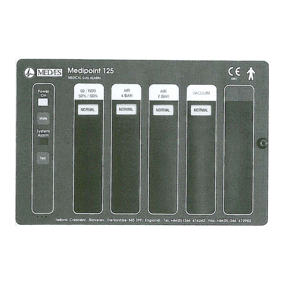
An individual Medipoint 125 alarm panel displays up to 5 gas services in a ‘normal’ and ‘4 stage’ alarm conditions, or may be used to display a maximum of 20 ‘traditional’... -
Page 7: Visual Displays
1. DESCRIPTION AND TABLE 1 : MEDIPOINT 125 – DIMENSIONS OPERATION Alarm Panel Bezel 1.3 Alarm Panels Height (mm) 196.0 246.0 continued Length (mm) 260.0 310.0 Depth (mm) 61.2 18 swg Chase depth (mm) 45.0 Gas service legends are printed on acetate strips, which slide into the alarm panel front cover through the uppermost internal slots. -
Page 8: Test And Mute Switches
1.7 Printed circuit boards Two printed circuit boards (pcb’s) are fitted inside a Medipoint 125 Medical gas area alarm, ie a power supply pcb and a light display pcb. All components are mounted on these pcb’s which are interconnected by means of a multi-way ribbon cable and polarised connector. -
Page 9: Power Supply Printed Circuit Board
1. DESCRIPTION AND 1.7.2 Power supply printed circuit board The power supply pcb is retained inside the alarm panel back box with OPERATION four retaining studs and connects to the light display pcb multi-way ribbon cable by polarised connectors. The power supply pcb 1.7 Printed circuit boards incorporates four mains terminals (EENL) connected to matching continued... -
Page 10: Remote Audible Warning Devices
50mA. 1.11 Operation of the alarm system Each Medipoint 125 medical gas alarm panel is connected to the mains electrical power supply and operates by 15V and 5V d.c. circuits from it’s integral transformer. Service failure sensors provide the input to initiate both the visual displays and audible warning. - Page 11 LED flashes at a faster rate, this indicates a short circuit. If the respective alarm LED flashes at a slower rate, this indicates an open circuit. This facility is designed to aid fault diagnosis. The Medipoint 125 medical gas central alarm system logic is detailed at Table 2 and 3.
-
Page 12: Programming Of The Alarm System
4 alarm conditions with an audible on all alarm conditions. 8-way DIL switch SW6 sets details specific to each panel. Rotary switch SW7 sets the panel ID. Similar switches are on the rear of the relay board (Fig. 2) in a Medipoint 125 relay interface panel. - Page 13 Figure 1 Light Display – Switch positions...
- Page 14 SW6-7 NB if the central mute facility is utilised then the master panel must be set to central mute ON. TABLE 5 : MEDIPOINT 125 RELAY INTERFACE PROGRAMMING Switch Setting/description Relay channel 1 Off, gas display channel not used 1-9 -...
- Page 15 Figure 2 Relay Panel – Switch positions...
-
Page 16: Commissioning
2. COMMISSIONING 2.1 Introduction Commissioning of the Medipoint 125 medical gas central alarm installation is carried out in full after initial installation and the appropriate sections must be carried out after a major component change. The object of commissioning is to ensure that all components are serviceable and correctly programmed. -
Page 17: System Alarm Indication. Check
2. COMMISSIONING 2.10 SYSTEM ALARM indication. Check The procedure for checking that the SYSTEM ALARM circuits are operating continued correctly is as follows, and should be carried out on all alarm panels:- 2.10.1 Electrical power supply. Switch OFF 2.10.2 Indications. Check. Check that POWER ON LED is extinguished and SYSTEM ALARM LED is illuminated (flashing), accompanied by an audible warning, after 15 seconds. -
Page 18: Operating Instructions
3. OPERATING WARNING… ANY ALARM CONDITION MUST BE INVESTIGATED AND THE GAS SERVICE RETURNED TO INSTRUCTIONS NORMAL AS SOON AS POSSIBLE CAUTION… The TEST and MUTE switches must only be operated by gentle finger pressure. Operation by use of instruments, tools or other implements will cause damage to the switch. -
Page 19: Maintenance
4. MAINTENANCE 4.1 Introduction Medipoint 125 medipoint gas central alarm systems are designed to operate with the minimum of maintenance, however regular minor maintenance operations are recommended to prove the system integrity. Maintenance operations are carried out in accordance with the planned preventative maintenance contract purchased by the customer. -
Page 20: Annual Inspection
4. MAINTENANCE 4.5.9 Remote audible. Check. If a remote audible is connected to the alarm panel, ensure that whilst 4.5 Quarterly inspection carrying out Step 4.5.5 remote audible warning operates correctly. continued 4.5.10 Relay interface. Check. If the relay interface is connected, ensure that whilst carrying out Step 4.5.5 the relay contacts operate (open) with any failure display. -
Page 21: Replacing A Power Supply Printed Circuit Board
4. MAINTENANCE 4.8.1 Electrical power supply. Switch OFF. 4.8 Replacing a light display printed 4.8.2 Alarm panel front cover. Open. circuit board 4.8.3 Light display pcb. Disconnect. continued Disconnect the multi-way ribbon connector at the power supply pcb. Disconnect the audible from the light display pcb. 4.8.4 Light display pcb. -
Page 22: Replacing A Back Up Battery
4. MAINTENANCE 4.9.8 Electrical power supply terminal. Reconnect. Plug in the power supply connector. Refit clear plastic cover. 4.9 Replacing a power supply printed circuit board 4.9.9 Terminals. Reconnect. Plug in all the other terminals in the respective positions from which continued they were unplugged. -
Page 23: Fault Diagnosis
5. FAULT DIAGNOSIS 5.1 Introduction The following tables detail possible defects/symptoms which may occur with the Medipoint 125 medical gas central alarm system, with the necessary rectification action. TABLE 6 : TEST OR MUTE SWITCH FAILS TO OPERATE Possible cause Remarks/rectification action 1. - Page 24 5. FAULT DIAGNOSIS TABLE 9 : SYSTEM ALARM/FAULT INDICATION WITH A SERVICEABLE GAS continued Possible cause Remarks/rectification action 1. Electrical power failure Check POWER ON indication is illuminated and other indications are normal 2. Gas service pressure . Independently check gas service incorrect pressure in area being monitored 3.
- Page 25 5. FAULT DIAGNOSIS TABLE 10 : REMOTE ALARM/RECORDING SYSTEM NOT OPERATING CORRECTLY continued Possible cause Remarks/rectification action 1. LK4 set incorrectly Check that the jumper on LK4 is set to the correct position (Sec 1.10) 2. Faulty interface relay With all gas services indicating NORMAL, check that continuity exists between both relay terminals (N/O and C) on power supply pcb.
- Page 26 5. FAULT DIAGNOSIS TABLE 13 : A GAS SERVICE DISPLAY FLASHING (INCLUDING NORMAL) WITH SYSTEM continued ALARM Notes… 1.Check status of other panels which display that particular gas service. If gas service display is flashing carry out steps 1-5 inclusive. 2.If the gas display on other alarm panel is illuminated carry out steps 4 and 5.
-
Page 27: Recommended Spares
6. RECOMMENDED Power supply pcb (100 to 127V a.c) ....Part No. 1828824 Power supply pcb (200 to 240V a.c) ....Part No. 1828801 SPARES Light display pcb . - Page 28 18/09/99 MEDÆS Limited - trading as Hill-Rom MEDÆS Telford Crescent, Staveley, Derbyshire S43 3PF, England Tel: +44 (0)1246 474242 Fax: +44 (0)1246 472982 e-mail: technical@medaes.co.uk Registered Office: MEDÆS Ltd., Telford Crescent, Staveley, Derbyshire S43 3PF Registration No. 2957933 English Register...
Need help?
Do you have a question about the Medipoint 125 and is the answer not in the manual?
Questions and answers
Intermittent random faults showing going back to normal for no set time and the returning in no set pattern, how to close to system down until fault is found