
Summary of Contents for SEW-Eurodrive DAE71B
- Page 1 *21308195_0816* Drive Technology \ Drive Automation \ System Integration \ Services Manual DAE70B/71B/72B Encoder Signal Split Box Edition 08/2016 21308195/EN...
- Page 2 SEW-EURODRIVE—Driving the world...
-
Page 3: Table Of Contents
Required preventive measure .............. 10 Device structure ........................ 11 Device properties and type designations .............. 11 3.1.1 DAE70B (INC) .................... 11 3.1.2 DAE71B (SSI) .................... 11 3.1.3 DAE72B (RES)..................... 11 Scope of delivery ...................... 12 3.2.1 Optional scope of delivery ................ 12 Nameplates........................ 19... - Page 4 Contents Connecting the position and velocity sensors............... 26 4.5.1 Before you start .................... 26 4.5.2 General installation notes for encoders............ 26 Service ............................. 27 Modification/changes to the device................ 27 Disposal ........................ 27 Replacement of the DAE70B/71B/72B encoder signal split box........ 27 Technical data......................... 28 General technical data .................... 28 Dimension drawing ....................... 28 DAE70B/71B/72B plug connectors ................ 29...
-
Page 5: General Information
General information About this documentation General information About this documentation This documentation is an integral part of the product. The documentation is written for all employees who assemble, install, start up, and service this product. Make sure this documentation is accessible and legible. Ensure that persons respons- ible for the machinery and its operation as well as persons who work on the product independently have read through the documentation carefully and understood it. -
Page 6: Structure Of Embedded Safety Notes
General information Rights to claim under limited warranty Meaning of the hazard symbols The hazard symbols in the safety notes have the following meaning: Hazard symbol Meaning General hazard Warning of dangerous electrical voltage Warning of hot surfaces Warning of risk of crushing Warning of suspended load Warning of automatic restart 1.2.3... -
Page 7: Product Names And Trademarks
General information Product names and trademarks Product names and trademarks The brands and product names in this documentation are trademarks or registered trademarks of their respective titleholders. Copyright notice © 2016 SEW‑EURODRIVE. All rights reserved. Unauthorized reproduction, modifica- tion, distribution or any other use of the whole or any part of this documentation is strictly prohibited. -
Page 8: Safety Notes
Safety notes Preliminary information Safety notes Preliminary information The following general safety notes have the purpose to avoid injury and damage to property. They primarily apply to the use of products described in this documentation. If you use additional components also observe the relevant warning and safety notes. Operator's duties Make sure that the basic safety notes are read and observed. -
Page 9: Designated Use
Safety notes Designated use Specialist for elec- Any electronic work may only be performed by adequately skilled persons (electric- trotechnical work ally). Qualified electricians in the context of this documentation are persons familiar with electrical installation, startup, troubleshooting and servicing of the product who possess the following qualifications: •... -
Page 10: Restrictions Of Use
Safety notes Electrical connection Protect the product from excessive mechanical strain. The product and its mounted components must not protrude into the path of persons or vehicles. Ensure that com- ponents are not deformed and that insulation spaces are maintained, particularly dur- ing transportation. -
Page 11: Device Structure
– MOVIAXIS with MOVISAFE UCS..B (compact or multi-axis type) • Connection of the TF temperature sensor: The TF temperature sensor can be connected to terminal X26 of the DAE71B en- coder signal split box. 3.1.3 DAE72B (RES) • Splitting of the resolver signals for the following device combinations: ®... -
Page 12: Scope Of Delivery
Scope of delivery Scope of delivery DAE70B/71B/72B encoder signal split box. • Part number DAE70B (INK): 18243797 • Part number DAE71B (SSI): 18243800 • Part number DAE72B (RES): 28232232 3.2.1 Optional scope of delivery Cable sets 1 – 9 SEW‑EURODRIVE offers product-specific cable sets that simplify configuration. The encoder cables of each cable set have a fixed length of 1.5 m. - Page 13 Device structure Scope of delivery Cable set 4 Part num- Encoder Function cable ® 28203038 DAE83B Connection between DAE70B/71B and MOVISAFE DCS..B ® DAE84B Connection between DAE70B/71B and MOVIDRIVE ® • Cable set 5 (for connecting DAE70B/71B to MOVIDRIVE B with DIP11B and DE- ®...
- Page 14 Device structure Scope of delivery Cable set 9 Part num- Encoder Function cable ® 28230914 DAE87B Connection between DAE72B and MOVISAFE UCS..B ® DAE89B Connection between DAE72B and MOVIAXIS DAE..B encoder cable INFORMATION The length of the encoder cables listed here can be configured from 0.8 m to 6 m. •...
- Page 15 Device structure Scope of delivery DAE81B Connection Part number [II] D-sub socket, 15-pin D-sub connector, 15-pin ® 18166261 DAE70B/71B:X71 MOVIAXIS • MXA:X13 • XGH11A:X63 • XGS11A:X64 • DAE82B encoder cable [II] 4135054347 DAE82B Connection Part number [II] D-sub socket, 9-pin D-sub connector, 9-pin ®...
- Page 16 DIP11B:X62 • DAE85B encoder cable [II] 4135054347 DAE85B Connection Part number [II] D-sub socket, 9-pin D-sub connector, 9-pin ® 18174345 DAE71B:X72 MOVISAFE UCS14B/PS: • X7-2 • X8-2 • DAE86B encoder cable [II] 4135054347 Manual – DAE70B/71B/72B Encoder Signal Split Box...
- Page 17 Device structure Scope of delivery DAE86B Connection Part number [II] D-sub socket, 15-pin D-sub connector, 15-pin ® 18157351 DAE70B/71B:X71 MOVIDRIVE B: • DEU21B:X14 • DAE87B encoder cable [II] 4135054347 DAE87B Connection Part number [II] D-sub socket, 9-pin D-sub connector, 9-pin ®...
- Page 18 Device structure Scope of delivery [II] 4135054347 DAE89B Connection Part number [II] D-sub socket, 15-pin D-sub connector, 15-pin ® 18177743 DAE72B:X71 MOVIAXIS • MXA:X13 Manual – DAE70B/71B/72B Encoder Signal Split Box...
-
Page 19: Nameplates
D-76646 Bruchsal Made in Germany -10 ... +60 °C IP20 Splittbox INKR Status: 10 -- -- -- -- ML0001 9007204037416587 3.3.2 DAE71B (SSI) DAE71B Type: 0000100 18243800 D-76646 Bruchsal Made in Germany -10 ... +60 °C IP20 Splittbox Status: 10 -- -- -- --... -
Page 20: Dae70B/71B
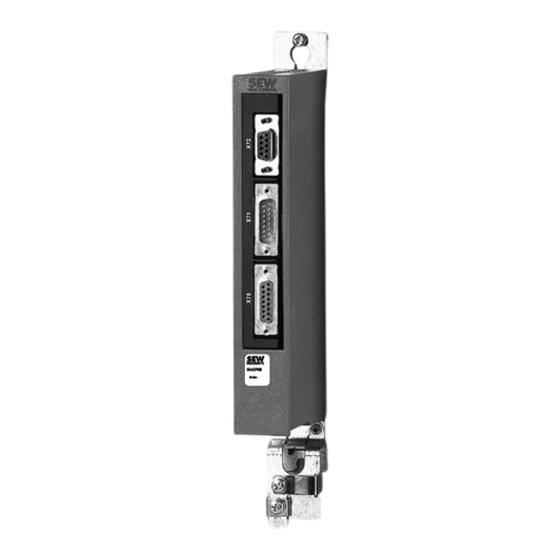
® Connection of MOVISAFE DCS..B, UCS..B ® ® Connection MOVIDRIVE B, MOVIAXIS DAE70B: Connection of TTL incremental encoder, SIN/COS encoder DAE71B: Connection of SSI absolute encoder Shield terminal Connection of TF temperature sensor Manual – DAE70B/71B/72B Encoder Signal Split Box... -
Page 21: Dae72B
Device structure Device structure 3.4.2 DAE72B OFF ON DAE72B 15973224075 View of the bottom of the device ® Connection of MOVISAFE UCS..B ® ® Connection MOVIDRIVE B, MOVIAXIS Resolver connection Shield terminal 8 DIP switches (in two rows, one behind the other, pos. 1 – 4) for switch- ®... -
Page 22: Installation
Part numbers • DAE70B encoder signal split box option (INC): 18243797 • DAE71B encoder signal split box option (SSI): 18243800 • DAE72B encoder signal split box option (RES): 28232232 INFORMATION You can only use the DAE70B/71B/72B option in combination with the matching en- coder cables (see chapter "Optional scope of delivery"). -
Page 23: Terminal Description
Installation Connection and terminal description of the DAE70B/71B/72B option 4.3.2 Terminal description Description Terminal DAE70B (INK) DAE71B (SSI) DAE72B (RES) DIP switch Assignment Assignment Assignment X26: TF connection X26:1 Shield Shield (Only for DAE70B/71B) X26:2 TF_REF TF_REF X26:3 X70: 15-pin D-sub socket... -
Page 24: Setting The Dip Switches At The Dae72B Encoder Signal Split Box
Installation Connection and terminal description of the DAE70B/71B/72B option Description Terminal DAE70B (INK) DAE71B (SSI) DAE72B (RES) DIP switch Assignment Assignment Assignment X72: 9-pin D-sub socket X72:1 N. C. N. C. N. C. • DAE70B/71B: X72:2 REF− ® Connection of MOVISAFE DCS..B... -
Page 25: Measures For Electromagnetic Compatibility (Emc)
Installation Measures for electromagnetic compatibility (EMC) ® For operation of the DAE72B encoder signal split box with MOVIDRIVE B, you have to set the DIP switches. Proceed as follows: 1. Open the DIP switch cover at the bottom of the DAE72B encoder signal split box. Set the DIP switches according to the label attached to the side of the housing (see the following figure). -
Page 26: Connecting The Position And Velocity Sensors
Installation Connecting the position and velocity sensors Connecting the position and velocity sensors 4.5.1 Before you start NOTICE Do not plug in or remove encoder connections during operation. Doing so can cause irreparable damage to the electrical components on the en- coder. -
Page 27: Service
Service Modification/changes to the device Service Modification/changes to the device • Hardware changes Changes to the module DAE70B/71B/72B option may only be carried out by SEW‑EURODRIVE. • Repair Only SEW‑EURODRIVE is authorized to repair the DAE70B/71B/72B option. INFORMATION Any right to claim under limited warranty becomes void if the user manipulates the device internally (e.g. -
Page 28: Technical Data
Technical data General technical data Technical data General technical data DAE70B/71B/72B Ambient temperature −10 °C to +60 °C Climate class 3K3 (EN 60721-3-3) Storage temperature −25 °C to +80 °C Degree of protection IP20 (EN 60529) Dimension drawing DAE70B 29.8 22.5 98.5 9007203390599435 Dimensions in mm. Manual –... -
Page 29: Dae70B/71B/72B Plug Connectors
Technical data DAE70B/71B/72B plug connectors DAE70B/71B/72B plug connectors 6.3.1 Connector assignment X26 Type: 3-pin Phoenix terminal, max. core cross section 1.5 mm Assignment DAE70B (incremental, SIN/COS) DAE71B (SSI) TF_REF TF_REF 6.3.2 X70 pin assignment Type: 15-pin D-sub socket. Assignment DAE70B (incremental, SIN/COS) -
Page 30: X71 Pin Assignment
Technical data DAE70B/71B/72B plug connectors 6.3.3 X71 pin assignment Type: 15-pin D-sub connector. Assignment DAE70B (incremental, SIN/COS) DAE71B (SSI) DAE72B (RES) CLK+ N. C. DATA + DATA + N. C. N. C. N. C. REF+ TF_REF TF_REF TF_REF N. C. -
Page 31: Index
DAE80B, 81B, 82B, 83B, 84B, 86B, 87B, 88B, 89B 14 Measures for electromagnetic compatibility (EMC) .. Designated use ............. 9 25 Device properties DAE70B............ 11 DAE71B............ 11 Nameplates DAE72B............ 11 DAE70B............ 19 Device structure .......... 11 DAE71B............ 19 DAE70B/71B .......... 20 DAE72B............ - Page 32 Index Notes Scope of delivery .......... 12 Meaning of the hazard symbols ....... 6 Optional ............ 12 Notes for using the DCS..B option ...... 22 Section-related safety notes ........ 5 Service .............. 27 Modification/changes to the device .... 27 Optional scope of delivery ........ 12 Replacement of the DAE70B/71B/72B encoder Cable sets 1 to 9 ..........
- Page 36 SEW-EURODRIVE—Driving the world SEW-EURODRIVE GmbH & Co KG P.O. Box 3023 76642 BRUCHSAL GERMANY Phone +49 7251 75-0 Fax +49 7251 75-1970 sew@sew-eurodrive.com www.sew-eurodrive.com...
Need help?
Do you have a question about the DAE71B and is the answer not in the manual?
Questions and answers