Table of Contents
Advertisement
Quick Links
Advertisement
Table of Contents

Summary of Contents for 3S IA0641
- Page 1 E-Class HD NVR IA0641/IB1281/IC1281 E-Class HD NVR Server Manual V1.0.
-
Page 2: Table Of Contents
E-Class NVR Table of Content Revision ..............................2 Terms and Conditions ..........................3 Product Contents ............................ 3 Symbols Used in This Manual ....................... 3 Hardware Installation and Parameter Settings ..................4 How to Create a RAID Group in LSI WEB BIOS ................18 How to create hot spare in LSI WebBIOS ................... -
Page 3: Revision
1. Storage operating system and video maybe corrupted or lost due to hard drive failure, computer viruses, or RAID controller failure. 3S strongly recommends that all data be periodically backed up. 3S does not assume any responsibility for data loss or recovery. -
Page 4: Terms And Conditions
Please verify the contents of the package is complete. Please refer to 3S documents on 3S official website for camera installation and network setup or confirm details with 3S technical support. Please read through this user manual for setup to avoid breakage due to mistakes during installation or assembly. -
Page 5: Hardware Installation And Parameter Settings
64 cameras, the IB0641 supports video streaming for 128 cameras. This NVR provides an intuitive interface for connecting cameras and setting up video and audio recording. This NVR supports all models of 3S Vision cameras. This NVR provides RAID level 5/6 and hot swappable drives for hard drive failure protection. -
Page 6: Safety Instructions
• Do Not expose system to harsh, humid environments. Electrical installation regulations must be followed. All maintenance work must follow 3s provided troubleshooting steps. Please read this manual before installing or operating the system. This document contains important safety instructions regarding its intended use. -
Page 7: Installation Notes
Warning: Equipment Installation: Only 3s approved technicians or installers should troubleshoot and install this product. Warning: Restricted Area: This unit is intended for installation in restricted access areas. A restricted access area can be accessed only through the use of a special tool, lock and key, or other means of security. -
Page 8: Hardware Description
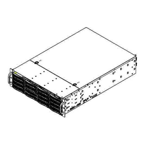
E-Class NVR Hardware Description ● Front of Device Control Panel Control Panel Buttons and Lights When this LED flashes, it indicates a failure in the redundant power Power Failure supply. Informational Light Status Status Description Solid Red An overheat condition has occurred in NVR. (This may be caused by cable congestion). - Page 9 E-Class NVR Control Panel Buttons and Lights Reset Reboot NVR server. Power Button The main power switch applies or removes primary power from the power supply to the JBOD Control Board but maintains standby power. Holding the power button for more than 3 seconds resets the JBOD.
- Page 10 Therefore, consideration should be given to installing air conditioning and ensuring fans in the server racks are providing sufficient air flow. (Note:Please refer to the 3S official website for specifications to help select a cabinet) - 9 -- V1.0.0.0...
-
Page 11: Rack Mounting
E-Class NVR Rack Mounting Please install the screw or retaining clips to the required position on the rack post. When initially installing the server to a rack, test that the rail locking tabs engage to prevent the server from being overextended. Have a rack lift in place as a precaution in case the test fails. - Page 12 E-Class NVR 2. Identify the left and right side inner rails. Place the correct inner rail on the side of the chassis, aligning the hooks of the chassis with the inner rail holes. Make sure the rail faces "outward" so that it will fit with the rack's mounting bracket.
- Page 13 E-Class NVR 3. Press upward on the locking tab at the rear end of the middle rail. Push the middle rail back into the outer rail. 4. Hang the hooks on the front of the outer rail onto the square holes on the front of the rack. Use screws to secure the outer rails to the rack.
- Page 14 E-Class NVR 5. Pull out the rear of the outer rail, adjusting the length until it just fits within the posts of the rack. - 13 -- V1.0.0.0...
- Page 15 E-Class NVR 6. Slide the chassis rails into the rack rails, keeping the pressure even on both sides. You may have to depress the locking tabs on both sides while inserting. When the server has been pushed completely into the rack, the locking tabs should "click" into the locked position. Middle Slide Press the latch on both sides of the front slide rail at the same time to push the NVR server into the cabinet.
- Page 16 E-Class NVR 7. (Optional) Insert and tighten the thumbscrews that hold the front of the server to the rack. Tighten Screw Tighten Screw Completed - 15 -- V1.0.0.0...
-
Page 17: Installing Hard Drives
E-Class NVR Installing Hard Drives • Before buy a hard drive, please go to 3S vision official site to check compatibility list to avoid incompatibility. http://www.3svision.com.tw/source/nvr-e-class-hdd-compatibility-list.html 1. Press the dark purple release button on the drive carrier. This extends the drive carrier handle. Use the handle to pull the drive out of the chassis. - Page 18 E-Class NVR 2. Remove the two screws securing the dummy drive to the drive carrier and remove the dummy drive. Dummy Drive Drive Carrier Take ESD precautions to avoid damage to hard disk. 3. Secure the hard drive to the carrier using six screws. Replace the drive carrier into the chassis. Make sure to close the drive carrier handle to lock the drive carrier into place.
-
Page 19: How To Create A Raid Group In Lsi Web Bios
E-Class NVR Connection Interface 1. Cameras use a DC12V / POE for power. Please refer to camera operation manual. Connect the keyboard and mouse to the USB 2.0 or PS2 connectors on the back of chassis. Connect the Monitor to the RGB or HDMI connector. Connect the network cables to the network card for video input and video output. - Page 20 E-Class NVR Choose option “Configuration Wizard”. Select the option “New Configuration” and then click “Next to continue. - 19 -- V1.0.0.0...
- Page 21 E-Class NVR A warning message will prompt to clear all RAID configuration and erase data. Click “Yes” to erase all configuration and continue. Select option “Virtual Drive Configuration” and click “Next” to continue. Select the drives to include in the “Drive Group” and click the “Add to Array” button. Note: Make sure not to select the Backplane it will cause an error.
- Page 22 E-Class NVR When finished adding hard drives to the hard drive group, click the “Accept DG” button. See illustration below. - 21 -- V1.0.0.0...
- Page 23 E-Class NVR Click the “Next” button to continue. - 22 -- V1.0.0.0...
- Page 24 Click “Add to SPAN” button to add drive group to SPAN, then click the “Next” button to continue. Select the RAID level RAID 0, RAID 5, or RAID 6. Note: 3S recommends RAID 5/6 for data - 23 -- V1.0.0.0...
- Page 25 E-Class NVR redundancy. Default RAID group settings. Note: 3S recommends accepting default settings. strip size: 64kb access policy: Read Policy: Ahead Write Policy: Write through IO policy: Direct Drive Cache: NoChange Disable BGI: After selecting RAID level and modifying RAID settings, click the “Accept” button to save changes.
- Page 26 E-Class NVR After confirming write through mode, the Virtual Drive screen will show, then click the “Next” button to continue. Note: Ignore RAID level 0 Click “Yes” button to save the configuration. - 25 -- V1.0.0.0...
- Page 27 E-Class NVR Select the new virtual drive group, select “Fast Initialize” option, then click the “Go” button to initialize the virtual drive group. Click “Yes” button to confirm data loss and to proceed with initialization. - 26 -- V1.0.0.0...
- Page 28 E-Class NVR After configuration is complete, the newly configured virtual drives will show in LSI WebBIOS screen. Click “Exit” to leave LSI WebBIOS configuration utility. When the JBOD reboots, it shows the new Virtual Drive(s). - 27 -- V1.0.0.0...
- Page 29 E-Class NVR On the E-Class NVR computer, open the disk management utility. Disk management will show the new virtual drive group, right-click on the unallocated drive and select “Initialize Disk”. The “Initialize Disk” window will show and automatically select “GPT” format (when the storage space is greater than 2TB).
- Page 30 E-Class NVR After initialization is complete, right-click on the disk and create a new volume. Click “Next” button on the New Simple Volume Wizard to continue. - 29 -- V1.0.0.0...
- Page 31 E-Class NVR Enter the storage space for the new volume. The default size is the maximum size of the disk group. Select the file system type “NTFS” and Allocation unit size. Note 3S recommends using the “Default” Allocation unit size. default - 30 -- V1.0.0.0...
- Page 32 E-Class NVR Click the “Finish” button to complete the New Volume Wizard. After completing the new volume wizard, the new volume will automatically start formatting in the background. The drive status shows “Healthy” after format completion. - 31 -- V1.0.0.0...
-
Page 33: How To Create Hot Spare In Lsi Webbios
2. If same model drive is not available ensure the replacement drive speed matches the original. 3.Confirm the replacement hard drive is listed on 3S visions hard drive compatibility list. Make sure there is enough storage space on the drive and there is an available slot in the chassis. - Page 34 E-Class NVR Select “Make Global HSP” to make hard drive hot spare. Click the “Go” button to confirm change. - 33 -- V1.0.0.0...
- Page 35 E-Class NVR How to Restore IOS for E-Class NVR 1.Insert the E-Class recovery USB into the USB drive on the NVR, then press the “Del” key during the boot process to enter the BIOS menu. After entering the BIOS screen, select the “Boot” tab, then set “Boot Option #1” to USB drive. Click the Save &...
- Page 36 E-Class NVR Select the 64G SATA DOM drive to install Windows 7 Embedded OS. (Must select the 64G SATA DOM drive that came with the server to install Windows OS on) Click “Next” to complete the installation. - 35 -- V1.0.0.0...
- Page 37 2. Confirm the power cord meets CE, UL, BSI safety regulations and the power cables are securely plugged into the power supplies. If the NVR still has no power after these steps, provide the following information to 3S Vision technical support.
- Page 38 E-Class NVR NVR, JBOD, and RAID card wiring Currently, 3SNVR supports two connection methods serial and parallel. The 3S E-Class NVR server needs to be equipped with a SAS interface card (SAS interface card is optional). Depending on which type of connection is used either serial or parallel will determine the type of SAS interface card to buy for the NVR.
- Page 39 E-Class NVR NVR Internal Wiring Instructions 1. Internal SAS cable (CBL-0281L) Connects the SAS connector on the RAID card to the SAS connector on the backplane (PRI_J1). Internal SAS cable (CBL-0167L) Connects to the SAS interface on the RAID card. Server and JBOD external SAS connections Use the SAS external cable (CBL-0166L) to connect the Server OUT (Data Input) side to the JBOD_1 IN (Data Out) side...
- Page 40 E-Class NVR Required cables and interface card 1. Install RAID card in NVR backplane and install cable CBL-0281L 2. Connect NVR and JBOD with cable CBL-0166L 3. NVR RAID card internal cable CBL-352L NVR Internal Wiring Instructions - 39 -- V1.0.0.0...
- Page 41 E-Class NVR 1. Internal SAS cable (CBL-0281L) Connects the SAS connector on the RAID card to the SAS connector on the backplane (PRI_J1). Internal SAS cable (CBL-0352L) Connects to the SAS interface on the RAID card. 3. The SAS connector on the same internal SAS cable (CBL-0352L) and the SAS connector on the backplane (PRI_J2) Server and JBOD external SAS connections Use the SAS external cable (CBL-0166L) to connect the OUT (data...
Need help?
Do you have a question about the IA0641 and is the answer not in the manual?
Questions and answers