Advertisement
Model 9210
Multichannel Lock-in Amplifier
Quick Start Guide
Introduction
Procedure – Hardware Setup
Procedure – Software Setup
This guide gives instructions for quickly setting up the SIGNAL RECOVERY
Model 9210 Precision Lock-in Amplifier and a procedure to verify that it has
arrived in good order with no shipping damage.
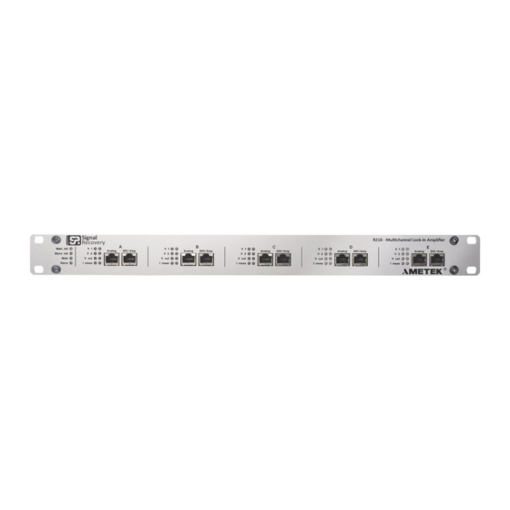
Figure 1, Model 9210 Lock-in Amplifier
1) After unpacking the box(es), check that you have the following items:
Model 9210 Lock-in Amplifier
Multi Country Line Power Cord
USB Memory Stick
2) Check the model 9210 for shipping damage. If any is noted,
SIGNAL RECOVERY should be notified immediately and a claim filed
with the carrier. The shipping container should be saved for inspection by the
carrier.
3) Check that the power switch on the rear of the model 9210 is set to the "Off"
position (O side pressed in).
4) Select the correct plug to suit the line power receptacle in your location and
use the IEC power cord to connect this plug to the power inlet socket on the
rear of the model 9210. The instrument uses a universal power supply so
unlike some other SIGNAL RECOVERY models there is no need to adjust a
line voltage setting or change a fuse.
5) Plug in the line power cord and turn on the model 9210's power switch. The
red Main LED on the front panel should light, followed other LEDs as the
instrument performs a self-check routine. The internal cooling fan should
also be heard to operate.
The supplied USB memory stick includes the MCL (multichannel lock in)
application software, the LabVIEW driver, and the product manual in PDF
format. To install the software, proceed as follows.
1) Plug the USB stick into a PC running Windows 7 or later, and use File
Explorer to navigate to the folder (figure 2):
SR9210\Application\Full Installer
Advertisement
Table of Contents

Related Manuals for Signal Recovery 9210


Summary of Contents for Signal Recovery 9210
-
Page 1: Quick Start Guide
The shipping container should be saved for inspection by the carrier. 3) Check that the power switch on the rear of the model 9210 is set to the “Off” position (O side pressed in). 4) Select the correct plug to suit the line power receptacle in your location and use the IEC power cord to connect this plug to the power inlet socket on the rear of the model 9210. - Page 2 2) Double click the Setup.exe file to start the MCL software installation. 3) After accepting a warning indicating the software is signed by AMETEK, Inc (the parent company of SIGNAL RECOVERY), the installation program will start, as shown in figure 3 below.
-
Page 3: Initial Checks
1) Plug one end of a USB A-B cable into the connector marked Main on the rear panel of the model 9210, and plug the other end into a free USB port on the computer. The MCL software installation program automatically installs any required drivers so there is no need to do this manually. - Page 4 Figure 5, MCL Software Main Display 5) The initial test procedure works by using a simple fixture consisting of a 1 k resistor which is driven by the 9210’s oscillator output, while the two voltage inputs measure the resulting voltage and the current monitoring stage measures the output current.
- Page 5 MODEL 9210 QUICK START GUIDE Figure 7, Model 9120 Test Fixture Connected to Module A Analog Input 7) In the software, select the Signal Recovery tab and then use the Config/View control to select the Output display. Set the controls to 1000 Hz, 1 V rms output, output enabled, and auto-range current measurement, as shown in figure 8, below.
- Page 6 MODEL 9210 QUICK START GUIDE 8) Use the Config/View control to select the Input V1 display (figure 9), and check the AC Coupling control, uncheck the GND controls, and check the Auto-range control. Check ac coupling Uncheck GND Check Auto-range...
- Page 7 Figure 13, MCL Software Input V1 Meter Display 14) If the model 9210 is fitted with more than one signal processing board (i.e. in slots B, C, D and/or E) then repeat the above tests for each slot after first plugging the test fixture into the slot being checked.
- Page 8 MODEL 9210 QUICK START GUIDE SIGNAL RECOVERY SIGNAL RECOVERY is part of df Advanced Measurement Technology, Inc 801 SOUTH ILLINOIS AVENUE 5 ASHVILLE WAY OAK RIDGE MOLLY MILLARS LANE TN 37831-2011 WOKINGHAM, BERKS RG41 2PL UNITED KINGDOM Phone: +1 865 483 2121...
Need help?
Do you have a question about the 9210 and is the answer not in the manual?
Questions and answers