
Subscribe to Our Youtube Channel
Summary of Contents for Steca StecaGrid Vision
- Page 1 Fernanzeige remote indication • télé-affichage display remoto • StecaGrid Vision Handbuch Manual Manuel Manuale • • • DE EN FR IT 734.144 | Z04 | 2012-11-22 Änderungen aufgrund technischer Verbesserungen vorbehalten!
-
Page 2: Table Of Contents
Contents General safety instructions ........30 Proper usage ............30 About this manual ..........31 Contents ..............31 Target group ............. 31 Symbols and markings ..........31 Scope of delivery ........... 32 Installation ............33 Mounting method ............ 33 Deinstallation ............33 Structure and function .......... -
Page 3: General Safety Instructions
• This device is not intended for children or persons with physical, sensory, or mental disabilities. Proper usage The StecaGrid Vision remote display, subsequently referred to as the remote display, is exclusively designed for connection to the following inverters: • StecaGrid 1800/2300/3010/3000/3600/4200 and StecaGrid 2020 • StecaGrid 8000 3ph/10000 3ph... -
Page 4: About This Manual
About this manual Contents This manual describes the installation, commissioning, operation and deinstallation of the remote display. The instructions of the respective manufacturer(s) must be observed for all components connected to the remote display. Target group The target group of this document are: • technical professionals installing, connecting, commissioning and de-installing the device. -
Page 5: Scope Of Delivery
Tab. 3: General labels used in the text Scope of delivery • 1 x StecaGrid Vision remote display • 1 x mains adapter plug • 2 x COMBICON plug connector: 2-pole, 3-pole • 1 x HARTING PushPull RJ45 10G, no. 09 45 145 1560: push-pull locking mechanism, can be wired without tools • 3 x dowels, 6 mm with screws... -
Page 6: Installation
Installation Mounting method Caution • Risk of electrical shock and fire if mounted in a damp environment! The mounting location must conform to the protection degree of the device; see Section 12, p. 54. • Danger of bodily injury and damage to the casing when drilling! Do not use the casing as a drilling template. -
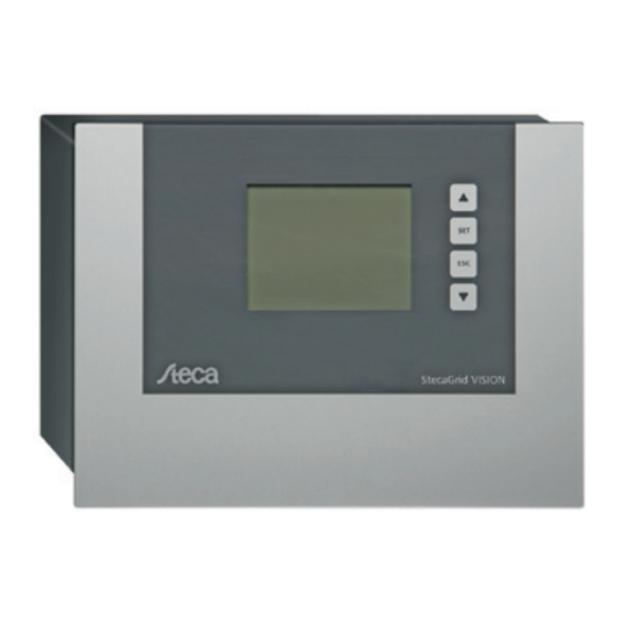
Page 7: Structure And Function
Structure and function Structure 6.1.1 Front Display UP button SET button ESC button DOWN button Fig. 1: Front with display and operating buttons 6.1.2 Connections on the underside Fig. 2: Connections on the underside No. Interface Description Connection for mains adapter plug for mains adapter plug supplied with... -
Page 8: Function
6.1.3 Cable connections Up to 20 inverters can be connected to the remote display. Communication between the remote display and the inverters takes place using a wired connection over an RS485 bus. More information is provided in the inverter manual. Function 6.2.1 Operating buttons... -
Page 9: Commissioning
Commissioning Note No specific sequence needs to be followed when connecting the power supply to the remote display and the data cables between the remote display and the inverters. Power supply The power supply must satisfy the following conditions: ✔ Rated voltage: 12 V ± 20 % ✔... -
Page 10: Basic Settings
Basic settings A number of basic settings must be performed on the newly connected remote display. This is done via a guided commissioning process. The following applies: • The guided commissioning process starts when: – basic settings have not yet been performed and the remote display is switched on for the 1st time. - Page 11 7.3.3 Entering the number of inverters and the addresses of the inverters In the next step you must enter the number of invert- ers and the addresses of the inverters in a list: 1. Use the UP and DOWN buttons to select the num- ber of inverters.
- Page 12 7.3.4 Country setting Note Setting the country also defines the local regulations for feeding electricity into the mains grid. In accordance with the grid feed safety regulations, the country can only be set once and cannot be subsequently changed. The remote display queries all inverters for the countries that are currently set and all countries that are supported.
-
Page 13: Switching On
When the power supply is connected to the remote display it first displays the start logo and then the System daily yield screen. If a malfunction exists then the Steca logo remains visible. System daily yield The System daily yield view provides an overview of the current state of all inverters. -
Page 14: Main Menu
Main menu Pressing the SET button in the System daily yield or Inverter daily yield screens will bring you to the main menu. You navigate through the menu entries using the UP and DOWN buttons. Pressing the SET button displays the submenu of the currently selected main menu entry. - Page 15 9.1.2 Yield The Yield submenu allows you to display the yield of the entire system or individual inverters. You can select different time periods: • System total • System year • System month • System day • Inverter total • Inverter year • Inverter month • Inverter day An hourglass symbol is displayed if not all information...
- Page 16 System month This menu item displays the summed yield of all invert- ers for the selected month. The yields for each day of the selected month are displayed as a bar chart. The number of days in the month are taken into account (30, 31 or 28/29).
-
Page 17: Settings
Inverter month This menu item displays the yield of the selected inverter for the current month. The yields for each day of the selected month are displayed as a bar chart. The number of days in the month are taken into account (30, 31 or 28/29). - Page 18 Language A list of languages supported by the remote display is displayed. The current language is selected. Use the UP and DOWN buttons to browse through the lan- guages and select one of these using the SET button. Country The country currently set for the connected inverters is displayed.
-
Page 19: Alarm
Inverter Addresses This menu item allows you to set the number of con- nected inverters and define their individual addresses. Use the UP and DOWN buttons to set the desired address value. Pressing the SET button confirms the value and moves to the next setting. The number of inverters must be set first. -
Page 20: Information
— Assembly CommAdapt • Hardware version — Assembly SYS — Assembly CommAdapt SET jumps to the next inverter. Company This item displays the Steca contact information. DOWN For display use the button to scroll down. 734.144 | Z04 | 2012-11-22... -
Page 21: Errors/Warnings
Errors/Warnings This menu item allows you to display the last errors logged for the System or Inverter. 9.5.1 System All currently logged remote display errors are shown here in a list. Both confirmed and non-confirmed er- rors are listed. You can use the UP and DOWN buttons to scroll through the list. -
Page 22: Messages
Messages 11.1 Error messages Error messages are generated either by the inverters or the remote display and are displayed as follows: 11.1.1 Error message types There are 3 types of error message: • Type Information I The inverter has detected an error that does not affect the feed-in process. The user must take action to correct the error. - Page 23 11.1.3 Inverter error messages Perma- Error message Description Type nent Grid voltage too The mains voltage of one or more phases at the inverter exceeds the per- missible value. The inverter must not feed into the grid. high Contact your installer. ...
- Page 24 Perma- Error message Description Type nent The inverter cannot or may not feed the grid at full power because the Derating: 10 average output voltage over a period of 10 minutes has been outside the minute average value > 30 min permissible tolerance range for over 30 minutes.
-
Page 25: Settings Screens
11.1.4 Remote display error messages W: <XX>% below average daily yield The test for low yields takes place at midnight (0:00 hours) each day. The following ap- plies: • The daily yield of each inverter is compared to the average daily yield of all inverters. • An alarm is triggered if an inverter has a yield greater than 0.001 Wh but less than the defined threshold value. - Page 26 11.2.3 Address setting The addressing is queried during initial commissioning and when an error occurs in the device internal storage; see Section 7, p. 36 onwards. 11.2.4 Country setting If settings are changed in the inverters, in some cases it may be necessary to set the country again;...
-
Page 27: Technical Data
1. Use UP / DOWN to select a country. Note: If your country is not displayed then select a country with values as close as possible to your country; see the inverter manual. 2. Press SET. The confirmation message is displayed (Fig. -
Page 28: Legal Guarantee
The guarantee only applies to defects in materials and workmanship, insofar as these can be attributed to inadequate professional ability on the part of Steca. Steca reserves the right at its own discretion to repair, adapt or replace the faulty prod- ucts. -
Page 29: Exclusion Of Liability
Improper installation of the system may result in damage to property and, as a result, to bodily injury. Therefore, Steca Elektronik GmbH assumes no responsibility and liability for loss, dam- age or costs which result or are in any way related to incorrect installation, improper operation and incorrect use and maintenance. - Page 30 Appendix Zertifikate • Certificates • Certificats • Certificati 734.144 | Z04 | 2012-11-22...
- Page 31 Appendix 734.144 | Z04 | 2012-11-22...
- Page 32 Appendix 734.144 | Z04 | 2012-11-22...
- Page 33 Appendix 734144 734.144 | Z04 | 2012-11-22...
Need help?
Do you have a question about the StecaGrid Vision and is the answer not in the manual?
Questions and answers