
Summary of Contents for Isel SK11
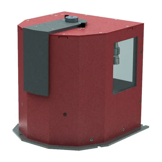
- Page 1 Germany AG, April 2019, deutsch Figure 1: Turned tool changing station SK20 Turned tool changing station SK11 and SK20 Assembly manual © isel Germany AG, April 2019, english...
- Page 2 Turned tool changing station SK11 and SK20 About this assembly manual Abbreviations used in this manual Machinery Directive 2006/42/EC EMC Directive 2004/108/EC EMCD Low Voltage Directive 2006/95/EC Symbols used in this manual Various symbols are used in this manual to draw your attention to important information / circumstances, and dangers.
- Page 3 CE safety guidelines must be applied until all corresponding requirements have been fulfilled. isel Germany AG assumes no warranty if you carry out any modifications of the turned tool changing station. Manufacturer: isel Germany AG Bürgermeister-Ebert-Strasse 40...
-
Page 4: Table Of Contents
Turned tool changing station SK20 ...................7 Connections ........................... 8 Electrical connection ......................8 Pneumatic connection ..................... 10 Assembly and commissioning ..................... 10 4.1 Assembly of turned tool changing station SK11, SK20 ............10 4.1.1 SK11 assembly ........................10 4.1.2 SK 20 assembly........................11 Establishing connections .................... -
Page 5: General Information
The SK11 and SK20 turned tool changing stations are space-saving tool storage units with tool slots arranged in a circle. The SK11 turned tool changing station is designed to hold and temporarily store up to 12 milling and/or machining tools with SK11 tool holding fixtures. The SK20 changing station can accommodate up to 14 milling and/or machining tools. - Page 6 Turned tool changing station SK11 and SK20 Work may only be carried out by authorised, qualified personnel in consideration of the regulations of the electrical and electronics industry, as well as accident prevention regulations. The mains plug must be pulled out before opening the housing and performing any work on the electrical installation.
-
Page 7: Product Description
14 storage slots for SK20 239100 6630 2.1.1 Turned tool changing station SK11 Powder-coated RAL3011 aluminium housing 12 type SK11 tool slots arranged in a circle Monitoring of tool slot and changer opening Integrated power electronics ... -
Page 8: Connections
3 Connections All turned tool changing stations are optimised for operation with isel control units. Connection cables may not be extended; otherwise the optimal operation of the SK11 or SK20 turned tool changer can no longer be guaranteed. Electrical connection *We reserve the right to technical modifications No. - Page 9 Turned tool changing station SK11 and SK20 3. System IN plug connection Signal Identification Stop1 IN CH1 standstill monitor Enable Tool changer release n.c. not assigned +24V Logic +24V voltage supply GND 24V Logic GND voltage supply + Power Motor +24V voltage supply...
-
Page 10: Pneumatic Connection
Required hose diameter 6mm. 4 Assembly and commissioning 4.1 Assembly of turned tool changing station SK11, SK20 Ensure that you have a stable and secure foundation for the turned tool changing station prior to commissioning. Avoid collision with other components of the machine. -
Page 11: Sk 20 Assembly
Turned tool changing station SK11 and SK20 4.1.2 SK 20 assembly Fasten all six fastening points on the turned changer to the mounting area of your machine with machine screws (not included in the scope of supply) and ensure that it is flat and level. - Page 12 Turned tool changing station SK11 and SK20 System IN interface System IN Connect the 15 pin Sub D of the orange cable to the slot on the turned changer. Route the cable into the switch cabinet. Disconnect the black AMP plug strip, STOP1 OUT, STOP2 OUT, …...
- Page 13 Turned tool changing station SK11 and SK20 Connect the System OUT cable to the appropriate jack on the turned changer and route the cable to the SKM-S1.2-E safety circuit module in the switch cabinet. White and black wires are already connected at terminals X5:E1.3...
- Page 14 Turned tool changing station SK11 and SK20 Establishing voltage supply: The turned tool changing station also requires a 24V DC voltage supply. We recommend using a 24V power supply unit with at least 100 watts. The voltage connection must be made after...
- Page 15 Turned tool changing station SK11 and SK20 15 / 27 April 2019...
-
Page 16: Commissioning
Turned tool changing station SK11 and SK20 Commissioning Commissioning takes place with the isel ProNC software. You should check all settings and adapt them to your tool changer. Start ProNC, Settings Control unit Tool management Changing station 1 under the menu ->... - Page 17 Turned tool changing station SK11 and SK20 Determine the direction from which the tool changer should run. Specify the minimum clearances before critical movements here. Adjust the I/Os. For this purpose, pay attention to the Help in ProNC. 17 / 27...
- Page 18 Turned tool changing station SK11 and SK20 You configure your tool changer here. Enter the start and/or end position of the tool changer, specify the interface, and specify the individual tool slots. Also use the detailed Help in ProNC. Parameters...
- Page 19 1. However, the storage slots may also be freely assigned. tool positions Recommended arrangement of the tool storage slots in the SK11 turned tool changer with 12 storage slots. tool positions Recommended arrangement of the tool storage slots in the SK20 turned tool changer with 14 storage slots.
- Page 20 Turned tool changing station SK11 and SK20 Move the turned tool changer until storage slot 1 is centred in the tool change opening. Attention: Do not reach into the moving changing station. Danger of severe injury. For better control: Both tappets of the tool holder must be above the pressure plate of the ejection cylinder.
- Page 21 Turned tool changing station SK11 and SK20 Make fine adjustments for the changing process under the Options menu item. Set up the automatic tool measurement. Specify the reference heights of the individual tools. 21 / 27 April 2019...
- Page 22 Turned tool changing station SK11 and SK20 4.3.2 Saving and initialising the configuration After you have confirmed the configuration with Adopt, it should be saved under CNCWorkbench\Control\To olchange\TchUni . The folder CNCWorkbench\ is already on your computer. The settings are transmitted to the control unit with Close and Initialise, and the tool changer is now ready for operation.
-
Page 23: Technical Data
Turned tool changing station SK11 and SK20 5 Technical data Dimensional drawings: Figure 7: SK11 dimensional drawing Figure 8: SK20 dimensional drawing 23 / 27 April 2019... - Page 24 Turned tool changing station SK11 and SK20 Description Component SK11 SK20 Dimensions: LxWxH 224mm x 222mm x 228mm 360mm x 339.8mm x 271mm Minimum clear height: 250mm 300mm Maximum tool length: 60mm 75mm tool diameter: 22mm 36mm Tool holding device:...
-
Page 25: Maintenance And Service
Turned tool changing station SK11 and SK20 6 Maintenance and service Maintenance The SK11 and SK20 turned changing stations are maintenance-free. However, isel Germany AG recommends regular cleaning. Cleaning Switch off the machine and shut down the compressed air. Open the upper cover. -
Page 26: Faults
Return and collection systems Disposal of your SK11 and SK20 turned tool changing station, particularly the electronic components, may not take place with household waste. Local waste disposal companies have made the necessary disposal facilities available for this purpose. -
Page 27: April
VII, Part B. The manufacturer is obligated to electronic submission of this technical documentation to the national competent authorities upon request. Person authorised to compile the technical documentation: Christian Bley (CE coordinator, isel Germany AG) The product (partially completed machine) is intended for incorporation into a machine or combination with other partially completed machinery to form a machine in the sense of Machinery Directive 2006/42/EC, Article 1, Section (1), Letter a.
Need help?
Do you have a question about the SK11 and is the answer not in the manual?
Questions and answers