
Related Manuals for LittleMachineShop.com HiTorque 5100

Summary of Contents for LittleMachineShop.com HiTorque 5100
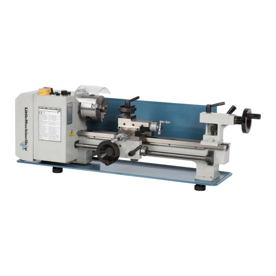
- Page 1 The premier source of tooling, parts, and accessories for bench top machinists. HiTorque 7x16 Mini Lathe Users Guide Model 5100 • Model 7350 Deluxe from LittleMachineShop.com...
- Page 2 © Copyright 2019 LittleMachineShop.com All rights reserved. Photos © Copyright 2019 PhotoBoost.com All rights reserved. Written by Chris Wood of LittleMachineShop.com Revision 2, August 2019 LittleMachineShop.com https://www.littlemachineshop.com 396 W. Washington Blvd. #500, Pasadena, CA 91103 (800) 981-9663 • Fax (626) 584-5844...
-
Page 3: Table Of Contents
Contents Introduction ................5 Specifications ................5 Safety Considerations ..............6 General Safety ................6 Lathe Safety ................6 Electrical Safety ................. 6 Machine Safety ................7 Features ..................8 Front View ................8 Rear View ................9 Accessories ................. 9 Cleaning ................... - Page 4 Maintenance ................21 Cleaning ................21 Lubrication ................21 Changing Chuck Jaws ..............23 Mounting Work in a 3-Jaw Chuck ............24 Grinding Tool Bits ................ 24 How to Grind Tool Bits ............... 26 Grind the Front Relief ..............26 Grind the Left Side Relief ............
-
Page 5: Introduction
Introduction This user’s guide covers care and operation of the LittleMachineShop.com HiTorque 7x16 Mini Lathe. Be sure to read and understand the safety guidelines presented in this book before using your HiTorque Mini Lathe. The HiTorque 7x16 Mini Lathe is available in two models: •... -
Page 6: Safety Considerations
Safety Considerations Always use common sense when using a power tool. Besides the general safety rules for any power tool, following also are specific considerations for the mini lathe. General Safety • Use common sense. Think through the results of your actions before you act. -
Page 7: Machine Safety
• Ensure that all components are properly grounded. The easiest way to ensure this is to plug your machines and devices into grounded outlets that you have tested. • Use caution when using liquids and electricity. Ensure that coolants and lubricants are kept away from high voltage electrical components. -
Page 8: Features
• Make sure the machine is on a flat, level surface that is capable of supporting the weight of the machine plus fixtures, vise, and workpiece. • Clamp work securely. Cutting forces are significant and can turn workpieces that are not secured into projectiles. •... -
Page 9: Rear View
Power feed forward/ Rear View neutral/reverse lever Accessories The following accessories come with the HiTorque Mini Lathe. • Chuck key for the 3-jaw chuck • Open end wrenches: 8 x 10 mm and 14 x 17 mm • Outside jaws for the 3-jaw chuck •... -
Page 10: Cleaning
Cleaning Your lathe will arrive coated with heavy oil to protect it from corrosion during shipment. Wipe off any excess with rags or paper towels, but leave a light coating in place. See “Lubrication” on page 21 for specific recommendations for lubricants. Assembly There are two things to do to assemble your lathe. -
Page 11: Operating Controls
the underside of wooden benches to prevent the bolt heads from pulling through. Operating Controls There are several controls used to operate the lathe. Become familiar with them before you use the lathe. Motor Controls 1. Power and emergency stop (E-stop) switch 2. -
Page 12: Power Feed Forward/Neutral/Reverse Lever
To power up the lathe: 1. Turn the speed control to the minimum speed position. 2. Place the forward/off/reverse switch in the off position. 3. Turn on the power switch by pressing the green button. To start the lathe: 1. Ensure that the speed control is set to the minimum speed position. 2. -
Page 13: Cross Slide Feed Handle
Cross Slide Feed Handle The cross slide feed handle moves the cross slide across the ways. Use this handle to advance the tool into the work and for facing cuts. The dial on this handle indicates the relative position of the cross slide. The graduated dial can be repositioned for convenience. -
Page 14: Compound Rest Rotation
To replace the battery: Each DRO uses a single CR2032 lithium battery (LittleMachineShop.com part number 4292). 1. On the bottom of the display unit, squeeze together the two tabs and then pull out the battery drawer. -
Page 15: Tailstock Locking Lever
To change the angle of the compound rest: 1. Using the compound rest feed handle, retract the compound rest until the locking socket head cap screws are exposed. 2. Loosen the two socket head cap screws. 3. Turn the compound rest to the desired angle. 4. -
Page 16: Carriage
Carriage The carriage is held on the ways by two adjustable retaining plates that are bolted to the bottom of the carriage. Carriage retainer There are several fasteners in the carriage retainers. The socket head cap screws are used to adjust the position of the retainers. The setscrews and lock nuts lock the adjustments in place. -
Page 17: Cross Slide Nut
Cross slide nut adjusters Cross slide gib adjusters To adjust the cross slide gibs: 1. Loosen the three lock nuts on the side of the cross slide. 2. Slightly loosen all three setscrews on the side of the cross slide. 3. -
Page 18: Compound Rest Gibs
Compound Rest Gibs The compound rest also incorporates a gib for adjustment. Compound rest adjusters Apron adjusters To adjust the compound rest gibs: 1. Loosen the three lock nuts on the side of the compound rest. 2. Slightly loosen all three setscrews on the side of the compound rest. 3. -
Page 19: Half Nuts
Tailstock adjustment Tailstock adjustment setscrew cap screw To adjust the tailstock position: 1. Remove the 3-jaw chuck from the lathe spindle. 2. Put a 3 Morse taper dead center in the spindle. 3. Remove the tailstock from the lathe. 4. Loosen the tailstock adjustment cap screw. 5. -
Page 20: Lead Screw Mounting
To adjust the half nut gibs: • Tighten the three setscrews in the back edge of the apron to remove play from the half nuts. To adjust the half nut limit: 1. Loosen the lock nut on the bottom of the half nuts. 2. -
Page 21: Maintenance
To adjust the drive belt: 1. Unplug the power cord. 2. Remove the change gear cover. 3. Loosen the four motor mounting socket head cap screws. 4. While you push down on the motor pulley with your left thumb, tighten one socket head cap screw on each side of the motor. - Page 22 Chris’ Tip: You might have trouble finding Lubriplate 630-AA grease. Don’t worry about the brand name. Get white lithium grease. Every auto parts store and most hardware stores will have it. It’s also available at LittleMachineShop.com (part number 3984). The following points on your lathe require lubrication. Location...
-
Page 23: Changing Chuck Jaws
Location Lubricant Frequency Notes Lead screw Grease Yearly Also lube change gears as you use drive gears them. and bushings Carriage hand Grease Yearly wheel drive gears Tailstock quill Grease Yearly and screw The spindle and countershaft bearings are deep groove ball bearings that are shielded and do not require additional lubrication. -
Page 24: Mounting Work In A 3-Jaw Chuck
2. Place your right hand around the chuck to prevent the jaws from falling out. 3. With your left hand, turn the lathe chuck key counter clockwise to open the jaws. 4. The jaws will come loose from the chuck, one at a time, when about half the length is exposed beyond the diameter of the chuck. - Page 25 Before diving in, there are some terms you need to understand. The illustration below shows these terms. First, notice that there are two cutting edges on the tool bit. There is a cutting edge on the end of the tool bit called the front cutting edge. There is also a cutting edge on the side of the tool.
-
Page 26: How To Grind Tool Bits
Back rake The back rake produces the front cutting edge that cuts into the workpiece. Front relief Front relief provides clearance for the front cutting edge. Without front relief, the front of the tool bit would hit the workpiece and not allow the cutting edge to penetrate the workpiece. -
Page 27: Adjusting Tool Bit Height
Adjusting Tool Bit Height The cutting edge of the tool bit should almost always be set to the center height of the lathe spindle. There are several methods for checking the height of the tool bit. Perhaps the simplest way is to place a thin strip of metal, such as a steel rule or feeler gage, between the workpiece and the point of the tool bit. -
Page 28: Turning With Power Feed
3. Move the carriage so that the tool bit is near the right end of the workpiece. 4. Turn the lathe on. Adjust the speed to an appropriate speed for the material and diameter you are working on. The LittleMachineShop.com Web site has a calculator to help you determine appropriate cutting speeds at https://littlemachineshop.com/mobile/menu.php. -
Page 29: Facing
6. Turn the lathe on. Adjust the speed to an appropriate speed for the material and diameter you are working on. The LittleMachineShop.com Web site has a calculator to help you determine appropriate cutting speeds at https://littlemachineshop.com/mobile/menu.php. -
Page 30: Turning Angles
Turning Angles There are several methods of turning angles or tapers. • For large angles of short length, such as a chamfer, turn the compound rest to the angle you want. Advance the tool across the work with the compound rest, and advance the tool into the work with the cross slide or the carriage. -
Page 31: Change Gears
Change Gears The series of gears that drive the lead screw are called change gears because you change them to turn different thread pitches. There are 4 positions for the change gears, commonly called A, B, C and D. A This is the top change gear position. When you received your lathe it had a 20 tooth metal gear in this position. - Page 32 Any gear 1.75 Any gear Any gear Any gear Any gear Any gear Any gear Any gear Any gear Any gear Any gear Any gear The LittleMachineShop.com Web site has a calculator to help you select the correct gears at https://littlemachineshop.com/reference/change_gears.php.
- Page 33 For normal turning, use the following gears. 20 80 20 80 The change gears are commonly tight on the shaft when new. You might need to use a screwdriver behind them to pry them off. Gear positions B and C are on a hollow shaft that comes off easily when the retaining socket head cap screw is removed.
-
Page 34: Threading Dial
12. Use a 14 mm end wrench to tighten the nut on the arc below and behind the gear in position D. 13. Use a 10 mm end wrench to tighten the nut that is on the back end of the shaft in position B-C. -
Page 35: Tool Bit
Threads Dial Threads Dial per inch divisions per inch divisions 1, 3, 5, 7 1, 5 1, 3, 5, 7 1, 5 1, 3, 5, 7 1, 5 1, 5 1, 3, 5, 7 1, 3, 5, 7 1, 5 1, 3, 5, 7 Tool Bit For threading, the tool bit is ground to the profile of the thread. -
Page 36: Compound Angle
Compound Angle Set the compound rest at a 29.5° angle from a line perpendicular to the axis of the lathe. This allows you to advance the tool with the compound rest. At this angle the tool cuts only on the left side of the thread form. This helps prevent chatter that might result from cutting the entire V form of the thread at once. -
Page 37: Threading Process
3. Align the tool bit to the sides of the V-shaped cutout in the side of the center gage. 4. Secure the tool bit in position. 5. Advance the tool bit until the point just makes contact with the workpiece. 6. -
Page 38: Common Accessories
You will soon find that the purchase of a lathe is just an initial step. There are many tools and accessories that you will need to get full use from your lathe. LittleMachineShop.com carries a full selection of accessories. Following are some common accessories used with the mini lathe, a small sampling of the complete LittleMachineShop.com line. -
Page 39: Indexable Turning Tools
You can resume work with no further adjustments. Indexable inserts are pre-sharpened. LittleMachineShop.com part number 1669. This set of indexable turning tools includes 5 tools (AR, AL, BR, BL, TE), wrenches, and extra screws. -
Page 40: Faceplate
3-jaw chuck. You can offset work in a 4- jaw chuck by clamping it off center. LittleMachineShop.com part number 1588. 4" 4-jaw chuck. Each jaw is independently adjustable and reversible. This set includes a chuck key and reversible jaws. -
Page 41: Steady Rest And Follower Rest
The steady rest is LittleMachineShop.com part number 1197, which can support work up to 1" in diameter. LittleMachineShop.com part number 4673 has a capacity of 2". The follower rest is LittleMachineShop.com part number 1198. -
Page 42: Parts Diagram
Parts Diagram... -
Page 43: Parts List
Parts List Item Description Qty. Item Description Qty. Bearing 6206- 1219 Screw M4x12 1530 Washer M8 1586 Cover 4422 Lock washer M6 2176 Screw M5x12 1532 Screw M6x10 Spindle gear 1320 Screw M8x20 1544 Nut M27x1.5 1329 Saddle 1389 Pulley 4040 Saddle retainer 1388... - Page 44 Item Description Qty. Item Description Qty. Gear 11/54 1378 Tailstock 1996 casting Half nut cam 1374 Tailstock base 1996 Half nuts 1373 Foot 4052 Gear 24 1379 Washer Hand wheel 1380 Tailstock screw 1304 Handle 1381 Retainer 1305 Gib, half nut 1371 Quill 1306...
- Page 45 Item Description Qty. Item Description Qty. Screw M6x20 1541 Key 3x8 mm 1357 Key 3x16 mm 1297 Gear 45T 1321 Spacer 1903 Gear mount 1358 Screw M3x10 1528 Screw M5x20 1535 Rubber foot 1294 Key 3x6 mm 5341 Screw M6x16 Gear 20T 1359 Screw M5x20...
-
Page 46: Dro Parts
Item Description Qty. Screw (H type) Apron shield 2960 Rivet M2x4 1988 Threading dial 1368 housing Indicator 1366 Shaft 1367 Screw DRO Parts Description Readout, DRO 5673 Retainer, DRO Cross Slide 2371 Screw Screw, DRO Cross Slide 2368 Retainer, DRO Compound 2372 Rest Screw Screw, DRO Compound Rest... -
Page 47: Wiring Diagram
Wiring Diagram...
Need help?
Do you have a question about the HiTorque 5100 and is the answer not in the manual?
Questions and answers