
Summary of Contents for CRISTAL CCLP-Modbus
- Page 1 CCLP-Modbus (Version 3.1.1) 2016-01-20 Martin Labbé, eng. Cristal Contrôles Ltd 2025 Lavoisier, Local 135 Québec, (Québec) Canada G1N 4L6 Ph. 418-681-9590 - Fax 418-681-7393 http://www.cristalcontrols.com...
-
Page 2: Table Of Contents
3.3. Modbus ....................15 ModbusAddr ....................16 ModbusBaud ....................16 ModbusDelay ....................16 ModbusCmdEvent ..................16 ModbusStats ....................16 3.4. CAN ....................... 17 2016-01-20 Cristal Contrôles Ltd 2025 Lavoisier, Local 135 Québec, (Québec) Canada G1N 4L6 Ph. 418-681-9590 - Fax 418-681-7393 http://www.cristalcontrols.com... - Page 3 Hardware specifications ................32 6.1. LED ......................32 6.2. Dip switches ................... 32 6.3. Jumpers ....................32 6.4. Dimensions .................... 33 2016-01-20 Cristal Contrôles Ltd 2025 Lavoisier, Local 135 Québec, (Québec) Canada G1N 4L6 Ph. 418-681-9590 - Fax 418-681-7393 http://www.cristalcontrols.com...
- Page 4 List of figures Figure 1 - PCB CCLP-Modbus ................5 Figure 2 - Power supply wiring ................7 Figure 3 - CAN terminating resistor ............... 8 Figure 4 - CAN network wiring ................9 Figure 5 - RS-485 Bias and terminating resistor ..........11 Figure 6 - Web panel interface ................
-
Page 5: Product Description
1. Product description The CCLP-Modbus is a communication card designed to interface up to 4 Cristal Controls relays scanners model CCLS-4016 within a low-voltage lighting relay panel. With the CCLP-Modbus, CCLS-4016 are accessible from the Modbus protocol. CCLP-1664 terminology indicates a complete relay panel. -
Page 6: Typical Wiring
2. Typical wiring These guidelines must be followed when the CCLP-Modbus and CCLS-4016 relays scanners are installed on site. Wrong wiring may damage the CCLP- Modbus and the CCLS-4016. 2.1. Power Supply The CCLP-Modbus controller and the CCLS-4016 relays scanners are half-wave power supplies. -
Page 7: Figure 2 - Power Supply Wiring
CIN3-4 CCLS-4016 #2 INPUT SELECT L24N24 IN3 IN4 CIN1-2 CIN3-4 CCLS-4016 #1 CCLP-MODBUS 24 VAC Figure 2 - Power supply wiring 2016-01-20 Cristal Contrôles Ltd 2025 Lavoisier, Local 135 Québec, (Québec) Canada G1N 4L6 Ph. 418-681-9590 - Fax 418-681-7393 http://www.cristalcontrols.com... -
Page 8: Internal Network (Can)
Low capacitance cable for network communication such as Anixter 316-023- 1802-FR-05 or Cerco Cable AT-HOM29 must be used. 2016-01-20 Cristal Contrôles Ltd 2025 Lavoisier, Local 135 Québec, (Québec) Canada G1N 4L6 Ph. 418-681-9590 - Fax 418-681-7393... -
Page 9: Figure 4 - Can Network Wiring
Out 9-16 CCLS-4016 #2 Out 1-8 Out 9-16 CCLS-4016 #1 Power 24Vac 24 VAC Status CC-MIP Figure 4 - CAN network wiring 2016-01-20 Cristal Contrôles Ltd 2025 Lavoisier, Local 135 Québec, (Québec) Canada G1N 4L6 Ph. 418-681-9590 - Fax 418-681-7393 http://www.cristalcontrols.com... -
Page 10: Ethernet Ieee 802.3
2.4. RS-485 Modbus RTU slave Verify certain aspects when RS-485 Modbus RTU network option is selected. When the CCLP-Modbus is at the end of a RS-485 bus, installing jumper “Term” must activate the on-board 120-Ω terminating resistors. A 604-Ω biasing resistors may be enabled by installing jumpers “Bias A(+)”... -
Page 11: Figure 5 - Rs-485 Bias And Terminating Resistor
Install jumper for termination Install both jumpers for BIAS Figure 5 - RS-485 Bias and terminating resistor For more information, refer to the Cristal Controls manual “Setting up a RS-485 Network”. 2016-01-20 Cristal Contrôles Ltd 2025 Lavoisier, Local 135 Québec, (Québec) Canada G1N 4L6 Ph. -
Page 12: Configuration Console
3. Configuration console The serial port of the CCLP-Modbus is used for the initial configuration of the device. You can connect to the serial port using a standard straight DB-9 male to DB-9 female serial cable. HyperTerminal can be used. Hyper Terminal is... -
Page 13: Show
The last line let you diagnose your Ethernet connection. It will display the speed of your Ethernet link if it is "up". Version Displays version information of the CCLP-Modbus and the CCLS-4016 relay scanner. CCLP-1664-Modbus 3.1 Compiled on May 01 2012 14:33:48 Copyrights Cristal Controls Ltd. -
Page 14: Ethernet And Ip
3.2. Ethernet and IP This command allows changing the IP address of the CCLP-Modbus or enables the usage of a DHCP server. Type this command with the needed IP address or the text dhcp. ip 192.168.2.35 ip dhcp When the IP address is set, you will be asked to “Reboot” the device so the changes to take effect. -
Page 15: Ethspeed
Ethernet connectivity. 3.3. Modbus WARNING: A misuse of these settings can cause network communication problems of the CCLP-Modbus board and to other Modbus devices on the network. Consult your Modbus network administrator for the accurate parameters. -
Page 16: Modbusaddr
ModbusStats Display Modbus communication statistics. Use this command with the “reset” parameter to clear Modbus statistics. 2016-01-20 Cristal Contrôles Ltd 2025 Lavoisier, Local 135 Québec, (Québec) Canada G1N 4L6 Ph. 418-681-9590 - Fax 418-681-7393 http://www.cristalcontrols.com... -
Page 17: Can
You can control what type of CCLS-4016 relay scanner events will be recorded to the flash memory. By avoiding some type of information you can record other information for a longer period of time. Contact Cristal Controls if you need to use the logging feature of the CCLS-4016 relay scanner. Default setting, ‘’no message is being logged’’. -
Page 18: Lighting Panel
This is to send some commands to relays. It may allow checking proper communication between the CCLP-Modbus and the associated CCLS-4016 relay scanner. Following this command with a relay number from 1 to 64 and the action “on”, “off”, or “flick”. Sending a “flick” command activates the unoccupied mode (see section 4.2 Relays for more details). -
Page 19: Group
When a master controller is set, we monitor if communication with this master controller is maintained. When the communication is lost, we disable the 2016-01-20 Cristal Contrôles Ltd 2025 Lavoisier, Local 135 Québec, (Québec) Canada G1N 4L6 Ph. 418-681-9590 - Fax 418-681-7393... - Page 20 Sub-commands follow. initdelay : Set the used delay after a reset of the CCLP-Modbus. This delay can be used to give more time to the master controller after a power loss. If the master controller does not read the CCLP-Modbus during this delay, we consider there is a communication problem.
- Page 21 Relay(s) ON : 1 2 3 5 16 32 clear on/off : empty the relays list from the indicated list. masterctrl clear on 2016-01-20 Cristal Contrôles Ltd 2025 Lavoisier, Local 135 Québec, (Québec) Canada G1N 4L6 Ph. 418-681-9590 - Fax 418-681-7393 http://www.cristalcontrols.com...
-
Page 22: Communication - Modbus Registers
Current state of the Input state 01-16 programmable inputs. (4)0217 (bit field) 0x0000 0xFFFF 0x0000 Each bit represents the 2016-01-20 Cristal Contrôles Ltd 2025 Lavoisier, Local 135 Québec, (Québec) Canada G1N 4L6 Ph. 418-681-9590 - Fax 418-681-7393 http://www.cristalcontrols.com... - Page 23 0 = OFF relays. Allows access to the internal configuration of the groups. The (4)0801- ModBrowse software (4)0844 Groups Configuration allows the 2016-01-20 Cristal Contrôles Ltd 2025 Lavoisier, Local 135 Québec, (Québec) Canada G1N 4L6 Ph. 418-681-9590 - Fax 418-681-7393 http://www.cristalcontrols.com...
- Page 24 Allows access to the internal configuration. ModBrowse software can change this (4)0901- configuration through (4)0964 Relays Configuration these addresses. 2016-01-20 Cristal Contrôles Ltd 2025 Lavoisier, Local 135 Québec, (Québec) Canada G1N 4L6 Ph. 418-681-9590 - Fax 418-681-7393 http://www.cristalcontrols.com...
-
Page 25: Inputs
OFF permanently after the Flick Warn delay. During the Flick Warn delay, the relay state can be 2016-01-20 Cristal Contrôles Ltd 2025 Lavoisier, Local 135 Québec, (Québec) Canada G1N 4L6 Ph. -
Page 26: Groups
OFF, the register is at 0.0%. When all relays are ON, the register is at 100%. If some relays are ON and some are OFF, the register will return the 2016-01-20 Cristal Contrôles Ltd 2025 Lavoisier, Local 135 Québec, (Québec) Canada G1N 4L6 Ph. - Page 27 The unoccupied mode is also activated for all relays within the group. When writing “0” the occupied mode is activated for the relays within the group and no command is sent. 2016-01-20 Cristal Contrôles Ltd 2025 Lavoisier, Local 135 Québec, (Québec) Canada G1N 4L6 Ph. 418-681-9590 - Fax 418-681-7393...
-
Page 28: Ccls-4016 Addresses
When this delay expires, the off-schedule mode for all relays is disabled. “ON” and “OFF” commands can also be applied on the relays. Two delays are being used: the first one after the CCLP-Modbus startup and the second one after initial communication is established. On startups, a different 2016-01-20 Cristal Contrôles Ltd... - Page 29 After the initial delay, the second delay is used. 2016-01-20 Cristal Contrôles Ltd 2025 Lavoisier, Local 135 Québec, (Québec) Canada G1N 4L6 Ph. 418-681-9590 - Fax 418-681-7393...
-
Page 30: Web Interface
5. Web Interface The CCLP-Modbus controller has a web interface that can be used for diagnostics. Simply type the IP address of your controller into your favorite web browser. If you select “Panel” from the top menu, you will see a large page showing all inputs and relays within the panel. -
Page 31: Figure 6 - Web Panel Interface
Figure 6 - Web panel interface 2016-01-20 Cristal Contrôles Ltd 2025 Lavoisier, Local 135 Québec, (Québec) Canada G1N 4L6 Ph. 418-681-9590 - Fax 418-681-7393 http://www.cristalcontrols.com... -
Page 32: Hardware Specifications
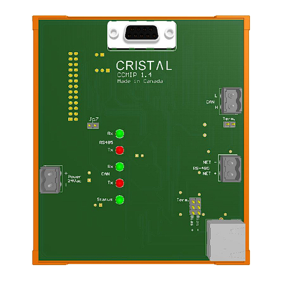
flash memory log storage : 512 kbytes, 100 000 write cycles 6.1. LED The led “Status” (LED3) should blink at 1 Hz when the CCLP-Modbus is normally operating. Other LED indicates communication activity respectively for RS-485, CAN, and Ethernet. -
Page 33: Dimensions
101mm CCMIP 1.4 Made in Canada Term. RS485 NET - RS-485 NET + Power 24Vac Term. Status Figure 7 - Dimensions 2016-01-20 Cristal Contrôles Ltd 2025 Lavoisier, Local 135 Québec, (Québec) Canada G1N 4L6 Ph. 418-681-9590 - Fax 418-681-7393 http://www.cristalcontrols.com... -
Page 34: Lavoisier, Local
Legal Disclaimer Any representation or reproduction, in whole or in part, made without the permission of Cristal Controls Ltd, is unlawful. Such unlawful representation or reproduction, made by any means, would be an infringement of copyright punished under the provisions of the copyright law. All products are registered trademarks of their respective companies. - Page 35 2 YEAR LIMITED WARRANTY CRISTAL CONTROLS warrants to the original user that its products will be free from defects in materials and workmanship for a period of two years after the date CRISTAL CONTROLS shipped such products. If any of CRISTAL CONTROLS’ products is found to be defective in material or workmanship...
Need help?
Do you have a question about the CCLP-Modbus and is the answer not in the manual?
Questions and answers