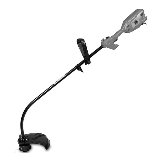
Summary of Contents for Fragram MCOM1256
- Page 1 1000W Line Trimmer MCOM1256 PLEASE READ THESE OPERATING INSTRUCTIONS BEFORE USING THE TOOL FOR THE FIRST TIME & KEEP THEM WITH THE TOOL AT ALL TIMES...
- Page 2 WARNING: When using power tools, basic safety precautions should always be taken to reduce the risk of fire, electric shock and personal injury. Also, please read and heed the advice given in the additional safety instructions. This appliance is not intended for use by persons (including children) with reduced physical, sensory or mental capabilities, or lack of experience and knowledge, unless they have been given supervision or instruction concerning use of the appliance by a person responsible for their safety.
-
Page 3: Specification
Disconnect the mains plug if the cord is damaged or entangled Wear eye and ear protection Keep bystanders away Warning! The blade still rotating after switch off SPECIFICATION 2. Technical Data Model type. MCOM1256 Rated Voltage: 230V~, 50Hz, Rated Power: 1000W Idling speed: 9000/min... - Page 4 KNOW YOUR LINE TRIMMER Before attempting to use this product, familiarize yourself with all operating features and safety rules. ERGONOMIC DESIGN The design of the trimmer provides for easy handling. It is designed for comfort and ease of grasp when operating in different positions and at different angles.
- Page 5 INSTALLING THE POWER HEAD TO THE ATTACHMENT See Figure 2. WARNING: Never install, remove, or adjust any attachment while power head is running. Failure to stop the engine can cause serious personal injury. The attachment connects to the power head by means of a coupler device. Loosen the knob on the coupler of the power head shaft and remove the end cap from the attachment.
-
Page 6: Attaching The Handle
ATTACHING THE HANDLE See Figure 4. A handle must be used for ensuring the best control and maximizing operator safety when using a brush cutter and trimmer. Hold the handle snugly in position on the shaft housing so that handle will be located to the operator’s left. Insert the shaft into the hole of bottom of handle. -
Page 7: Attaching The Grass Deflector
ATTACHING THE GRASS DEFLECTOR WARNING: The line cutting blade on the grass deflector is sharp. Avoid contact with the blade. Failure to avoid contact can result in serious personal injury. TO ATTACH THE STRAIGHT SHAFT GRASS DEFLECTOR See Figure 6. Remove the slotted hex head screw from the grass deflector. -
Page 8: Operation
WARNING: Do not allow familiarity with tools to make you careless. Remember that a careless fraction of a second is sufficient to inflict serious injury. WARNING: Always wear safety goggles or safety glasses with side shields when operating tools. Failure to do so could result in objects being thrown into your eyes, resulting in possible serious injury. -
Page 9: To Advance The Cutting Line Manually
TO ADVANCE THE CUTTING LINE MANUALLY Push the spool retainer down while pulling on string(s) to manually advance the string CUTTING TIPS See Figures 9. Avoid hot surfaces by always keeping the tool away from your body. The curved shaft trimmer cuts when passing the unit from right to left. The straight shaft trimmer cuts when passing the unit from left to right. -
Page 10: General Maintenance
MAINTENANCE WARNING: When servicing, use only identical replacement parts. Use of any other parts may create a hazard or cause product damage. WARNING: Always wear safety goggles or safety glasses with side shields during tool operation. If operation is dusty, also wear a dust mask. -
Page 11: String Replacement
Remove the empty spool from the string head. Keep the spring attached to the spool. To install the new spool; make sure the two strings are captured in the slots opposite each other on the new spool. Make sure the ends of each string are extended approximately 6 in. (152 mm) beyond each slot. Thread the strings into the eyelets in the string head. -
Page 12: Warranty
WARRANTY L&G Tool and Machinery Distributors warrant to the original purchaser only, that this power tool is free from defects in material and workmanship. Subject to certain exceptions, L&G Tools & Machinery Distributors will repair or replace any part on this power tool which, after examination, is determined by us to be defective in material or workmanship for a period of twenty four (24) months after the date of purchase unless otherwise noted.

Need help?
Do you have a question about the MCOM1256 and is the answer not in the manual?
Questions and answers