Viessmann Vitotrol 100 Installation And Service Instructions Manual
For the viessmann vitotronic 100
Hide thumbs
Also See for Vitotrol 100:
- Operating instructions for the system user (36 pages) ,
- Operating instructions manual (36 pages) ,
- Installation instructions for contractors (20 pages)

Related Manuals for Viessmann Vitotrol 100


Summary of Contents for Viessmann Vitotrol 100
- Page 1 VIESMANN Installation and service instructions for contractors Vitotrol 100 Type UTA Room thermostat for the Vitotronic 100 For applicability, see the last page VITOTROL 100 Please keep safe. 5862 628 GB 10/2012...
- Page 2 Safety instructions Safety instructions Please follow these safety instructions closely to prevent accidents and mate- rial losses. Safety instructions explained ■ all current safety regulations as defined by DIN, EN, DVGW, TRGI, Danger TRF, VDE and all locally applicable This symbol warns against the standards, risk of injury.
- Page 3 ■ When using gas as fuel, also close the For replacements, use only orig- main gas shut-off valve and safeguard inal spare parts from Viessmann against unauthorised reopening. or those which are approved by ■ Isolate the system from the power sup- Viessmann.
-
Page 4: Table Of Contents
Index Index Installation instructions Preparing for installation Installation site...................... Installation sequence Fitting the room thermostat.................. Electrical connection.................... Adjusting the room thermostat................Service instructions Specification....................... 12 Certificates Declaration of conformity..................13... -
Page 5: Preparing For Installation
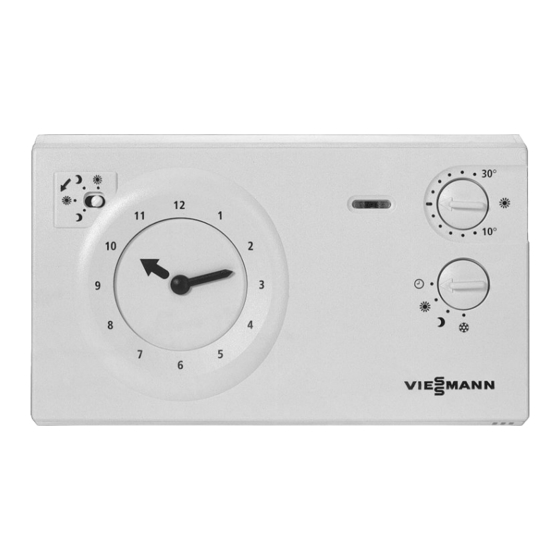
Preparing for installation Installation site ■ In the main living room on an internal wall opposite radiators. ■ Approximately 1.5 m above floor level. ■ Away from windows or doors. ■ Not on shelves or in recesses. ■ Away from heat sources (radiators, direct sunlight, fireplace, TV set etc.). -
Page 6: Installation Sequence
Installation sequence Fitting the room thermostat ° ° 90° Electrical connection Recommended connecting cable: ■ Without earth conductor: 3 x 1.5 mm² ■ With earth conductor: 4 x 1.5 mm²... - Page 7 Installation sequence Electrical connection (cont.) 90° ° ° Information on step 1 Press cables flat into the base. Wiring subject to the type of Vitotronic 100, see the following chap- ter.
- Page 8 Connection to the Vitotronic 100 with a terminal strip 1 2 3 4 5 6 7 8 9 10 11 12 A Terminal strip inside the D Vitotrol 100, type UTA Vitotronic 100, type KC3 Remove jumper across terminals 4 and...
-
Page 9: Adjusting The Room Thermostat
Installation sequence Electrical connection (cont.) Connection to the Vitotronic 100 with plug gH LS LR Adjusting the room thermostat Note Set room thermostat code, if required; see the installation and service instruc- tions for the Vitotronic control unit. 30° 10° 30°... - Page 10 Bring the controller for the electronic the electronic feedback. feedback into the required position using The Vitotrol 100 is set up at the factory a screwdriver. for standard mode. Only change this set- ting if the control unit must be adapted to the heating system.
- Page 11 "+" Repeat if required after the room tem- perature has stabilised. Note Following commissioning, the Vitotrol 100 needs around 1 hour to adjust to its ambient temperature. Users should only then make adjustments to suit their personal requirements.
-
Page 12: Specification
Specification Specification Rated voltage 230 V~/50 Hz Rated breaking capacity of the contact 6 A/250 V~ 1 A/250 V~ cosφ = 0.6 Switching hysteresis 0.4 to 1.5 K Power consumption Safety category IP rating IP 20 Ambient temperature ■ During operation 5 to 40 °C ■... -
Page 13: Certificates
Certificates Declaration of conformity We, Viessmann Werke GmbH&Co KG, D-35107 Allendorf, confirm as sole respon- sible body that the product Vitotrol 100, type UTA complies with the following standards: EN 60 730-1 EN 60 730-2-9 In accordance with the following Directives, this product is designated with _:... - Page 16 Applicability Serial No.: 7170149 Viessmann Werke GmbH&Co KG Viessmann Limited D-35107 Allendorf Hortonwood 30, Telford Telephone: +49 6452 70-0 Shropshire, TF1 7YP, GB Fax: +49 6452 70-2780 Telephone: +44 1952 675000 www.viessmann.com Fax: +44 1952 675040 E-mail: info-uk@viessmann.com...
Need help?
Do you have a question about the Vitotrol 100 and is the answer not in the manual?
Questions and answers