
Summary of Contents for SEW-Eurodrive MOVISAFE CS A Series
- Page 1 *28482271_0319* Drive Technology \ Drive Automation \ System Integration \ Services Manual ® MOVIDRIVE modular/system/technology ® MOVISAFE CS..A Safety Card (Version 2) Edition 03/2019 28482271/EN...
- Page 2 SEW-EURODRIVE—Driving the world...
-
Page 3: Table Of Contents
Table of contents Table of contents General information........................ 8 About this documentation .................... 8 Structure of the safety notes ................... 8 1.2.1 Meaning of signal words ................ 8 1.2.2 Structure of section-related safety notes............ 8 1.2.3 Structure of embedded safety notes .............. 9 Rights to claim under limited warranty ................ 9 Content of the documentation.................. 9 Other applicable documentation .................. 9... - Page 4 Table of contents 3.7.11 SSR – Safe Speed Range ................ 26 3.7.12 SSM – Safe Speed Monitoring.............. 27 3.7.13 SDI – Safe Direction.................. 27 3.7.14 SLI – Safely Limited Increment .............. 28 3.7.15 SBC – Safe Brake Control ................ 28 Safety concept of Assist CS.................. 29 3.8.1 Safety parameters ..................
- Page 5 Table of contents 7.5.1 Discrepancy monitoring................ 52 7.5.2 Interlocking .................... 52 7.5.3 Signal monitoring .................. 53 7.5.4 Pulsed voltage supply and crossfault monitoring ......... 53 7.5.5 Contact-equipped sensors (single-channel).......... 54 7.5.6 Sensors with contact (dual-channel) ............ 55 7.5.7 Active sensors (dual-channel) .............. 57 7.5.8 Sensors with semiconductor outputs (OSSD, dual-channel) .......
- Page 6 Table of contents 8.5.17 Test mode .................... 83 Startup of the safety card at the F-protocol.............. 84 8.6.1 Requirements for F-communication ............. 84 8.6.2 PROFIsafe protocol.................. 84 8.6.3 FSoE protocol .................... 85 ® 8.6.4 ISOFAST protocol.................. 86 Operating states...................... 87 8.7.1 Operating state "Operation" ................. 87 8.7.2 Operating state "Parameterization"...
- Page 7 Table of contents 11.1.7 Response time in case of limit value violation with safe communication ... 113 11.1.8 Deselection of a drive safety function via a safe digital input..... 114 11.1.9 Deselection of a drive safety function via safe communication.... 114 Service ...........................
-
Page 8: General Information
General information About this documentation General information About this documentation The current version of the documentation is the original. This documentation is an integral part of the product. The documentation is intended for all employees who perform work on the product. Make sure this documentation is accessible and legible. -
Page 9: Structure Of Embedded Safety Notes
General information Rights to claim under limited warranty Meaning of the hazard symbols The hazard symbols in the safety notes have the following meaning: Hazard symbol Meaning General hazard Warning of automatic restart 1.2.3 Structure of embedded safety notes Embedded safety notes are directly integrated into the instructions just before the de- scription of the dangerous action. -
Page 10: Decimal Separator In Numerical Values
General information Decimal separator in numerical values Decimal separator in numerical values In this document, a period is used to indicate the decimal separator. Example: 30.5 kg Copyright notice © 2019 SEW‑EURODRIVE. All rights reserved. Unauthorized reproduction, modifica- tion, distribution or any other use of the whole or any part of this documentation is strictly prohibited. -
Page 11: Safety Notes
Safety notes Preliminary information Safety notes Preliminary information The following general safety notes serve the purpose of preventing injury to persons and damage to property. They primarily apply to the use of products described in this documentation. If you use additional components, also observe the relevant warning and safety notes. -
Page 12: Designated Use
Safety notes Designated use Specialist for elec- Any electrotechnical work may only be performed by electrically skilled persons with a trotechnical work suitable education. Electrically skilled persons in the context of this documentation are persons familiar with electrical installation, startup, troubleshooting, and maintenance of the product who possess the following qualifications: •... -
Page 13: Installation/Assembly
Safety notes Installation/assembly If necessary, use suitable, sufficiently dimensioned handling equipment. Observe the information on climatic conditions in the chapter "Technical data" of the documentation. Installation/assembly Ensure that the product is installed and cooled according to the regulations in the doc- umentation. -
Page 14: Definitions
Safety notes Definitions Definitions • The designation "F-DI." stands for a safe input. • The designation "F-DO." stands for a safe output. • The designation "CS..A" is used as a generic term for all derivatives of the ® MOVISAFE CS product series. If a particular derivative is referred to in the manual, then the complete designation is used. -
Page 15: Safety Concept
Safety concept General Safety concept General ® The MOVISAFE CS..A safety card is a safe assembly with safe digital inputs and out- puts and, depending on the parameterization, safe communication. ® ® MOVISAFE CS..A is fully integrated in the MOVIDRIVE modular/system/technology ®... -
Page 16: Pluggable Safety Key
Safety concept Pluggable safety key Pluggable safety key ® The safety key must be inserted upon activation of the MOVISAFE CS..A safety card and may not be removed when the safety card is activated. ® The parameterization data of the MOVISAFE CS..A safety card is divided into appli- cation-related data and the key data set. -
Page 17: Drive Safety Functions According To En 61800-5-2
Safety concept Drive safety functions according to EN 61800-5-2 – 4 safe inputs – 2 safe dual-channel outputs ® MOVISAFE CSB31A safety card: – 4 safe inputs – 2 safe dual-channel outputs – Second encoder slot (not used for functional safety) ®... -
Page 18: Sto - Safe Torque Off
Safety concept Drive safety functions according to EN 61800-5-2 3.7.1 STO – Safe Torque Off If the STO function is activated, the drive inverter no longer supplies power to the mo- tor. As a result, the drive cannot generate torque. This drive safety function corres- ponds to a non-controlled stop according to EN 60204-1, stop category 0. -
Page 19: Ss1(C) - Safe Stop 1 With Time Control
Safety concept Drive safety functions according to EN 61800-5-2 3.7.2 SS1(c) – Safe Stop 1 with time control When the SS1(c) function is active, the inverter brings the motor to a standstill electri- cally. The drive safety function STO is triggered after a specified, safety-related time. This drive safety function corresponds to a controlled stop of the drive according to EN 60204-1, stop category 1. -
Page 20: Ss1(B) - Safe Stop 1 With Monitoring Of The Deceleration Ramp
Safety concept Drive safety functions according to EN 61800-5-2 3.7.3 SS1(b) – Safe Stop 1 with monitoring of the deceleration ramp When the SS1(b) function is active, the drive inverter brings the motor to a standstill e- lectrically. The deceleration is monitored. The STO drive safety function is triggered when the monitored deceleration is exceeded or when standstill is reached. -
Page 21: Ss1(A) - Safe Stop 1 With Control And Monitoring Of The Deceleration Ramp
Safety concept Drive safety functions according to EN 61800-5-2 3.7.4 SS1(a) – Safe Stop 1 with control and monitoring of the deceleration ramp When the SS1(a) function is active, the drive inverter brings the motor to a standstill e- lectrically. The deceleration behavior is not controlled and monitored in a safety-re- lated manner. -
Page 22: Ss2(C) - Safe Stop 2 With Time Control
Safety concept Drive safety functions according to EN 61800-5-2 3.7.5 SS2(c) – Safe Stop 2 with time control When the SS2(c) function is active, the drive inverter brings the motor to a standstill e- lectrically. At standstill, the drive inverter delivers the power to keep the motor in posi- tion. -
Page 23: Ss2(B) - Safe Stop 2 With Monitoring Of The Deceleration Ramp
Safety concept Drive safety functions according to EN 61800-5-2 3.7.6 SS2(b) – Safe Stop 2 with monitoring of the deceleration ramp When the SS2(b) function is active, the drive inverter brings the motor to a standstill e- lectrically. The deceleration is monitored. The position must be safely monitored after standstill (SOS function according to EN 61800-5-2). -
Page 24: Ss2(A) - Safe Stop 2 With Control And Monitoring Of The Deceleration Ramp
Safety concept Drive safety functions according to EN 61800-5-2 3.7.7 SS2(a) – Safe Stop 2 with control and monitoring of the deceleration ramp When the SS2(a) function is active, the drive inverter brings the motor to a standstill e- lectrically. The deceleration behavior is not controlled and monitored in a safety-re- lated manner. -
Page 25: Sos - Safe Operating Stop
Safety concept Drive safety functions according to EN 61800-5-2 3.7.8 SOS – Safe Operating Stop The SOS function prevents the motor from deviating from the stop position by more than a specified value. The drive inverter delivers the power to keep the motor in posi- tion. -
Page 26: Sls - Safely Limited Speed
Safety concept Drive safety functions according to EN 61800-5-2 3.7.10 SLS – Safely Limited Speed The SLS function prevents the drive from exceeding a specified speed. If the permit- ted speed is exceeded, the drive safety function will be triggered and an error re- sponse will be initiated at the same time. -
Page 27: Ssm - Safe Speed Monitoring
Safety concept Drive safety functions according to EN 61800-5-2 3.7.12 SSM – Safe Speed Monitoring The SSM function monitors whether the drive exceeds a specified speed. An exceed- ing of the allowed speed is signaled. 9007201225702923 = Drive safety function monitoring = Drive safety function trips = Speed = Time... -
Page 28: Sli - Safely Limited Increment
Safety concept Drive safety functions according to EN 61800-5-2 3.7.14 SLI – Safely Limited Increment The SLI function prevents a movement from exceeding a specified increment. If the limit value of the increment is not respected, the drive safety function will be triggered and an error response will be initiated at the same time. -
Page 29: Safety Concept Of Assist Cs
Safety concept Safety concept of Assist CS.. Safety concept of Assist CS.. 3.8.1 Safety parameters ® For parameterization of the drive safety functions, MOVISAFE CS.. A offers ad- justable safety parameters. The safety parameters determine the behavior of the corresponding drive safety func- tions and are therefore safety-related. -
Page 30: Safety Requirements
Safety requirements Installation requirements Safety requirements Installation requirements • Power cables and the safe control cables must be routed separately. • The wiring technology used must comply with the standard EN 60204-1. ® • The safe control cables of the MOVISAFE ... -
Page 31: Htl Encoder Cable
Safety requirements Sensor and actuator requirements – Differential signal pairs (e.g. the track signals A and A, B and B, C and C, Data + and Data-) must be routed via twisted cores. – The encoder cable may exhibit the following maximum capacitances per unit length: Capacitance per unit length core / core: CA’ = 70 pF/m Capacitance per unit length core / shield: CS’ = 120 pF/m... -
Page 32: Requirements For Stopping In An Emergency According To En 60204-1 (Emergency Stop)
Safety requirements Requirements for stopping in an emergency according to EN 60204-1 (emergency stop) ® For MOVIDRIVE applications with safe torque off • as per stop category 0, 1, or 2 in accordance with EN 60204-1, • and to prevent unexpected startup in accordance with EN ISO 14118, you must, as a general rule, carry out and document startup checks of the disconnect- ing device and the correct wiring. -
Page 33: Quantization Error
Safety requirements Encoder requirements WARNING Loss of the safety function due to use of out-of-date AS7W or AG7W safety en- coders, e.g. in existing systems. Severe or fatal injuries ® ü Use of the following safety encoders is not permitted with the MOVISAFE CS..A safety cards: •... -
Page 34: Counting Direction
Safety requirements Encoder requirements Error_v_EI7C FS = Actual speed x 1% Setting the Filter time speed HTL (8708.4) parameter makes it possible to filter the cal- culated speed via a sliding average value filter with the parameterized length. Acceleration The acceleration calculation determines the average acceleration in the time range set via the parameter Filter time acceleration (8708.2). -
Page 35: Requirements For Operation
Safety requirements Requirements for operation INFORMATION Exceeding the switch-off threshold results in a fault message in the safety card with the fault response "STO" within 11 ms for sine/cosine encoders or 13 ms for EI7C FS. The fault response is executed by the STO circuit within another 2 ms. Measures the application must ensure that the mechanical limit speed is not reached during this time (11 ms/13 ms). -
Page 36: Device Structure
Device structure Firmware version Device structure Firmware version ® ® The "MOVIDRIVE modular/system/technology – MOVISAFE CS..A safety card" ® manual (Version 2) applies to the MOVISAFE CS..A safety card as of firmware ver- sion 2.05. ® ® The "MOVIDRIVE modular/system ... -
Page 37: Nameplate
Device structure Nameplate Nameplate In addition to the device nameplates on the basic unit, a label is also attached to the rear of the CS..A safety card's front cover. The following figure shows an example la- bel. CSS31A PN#: 28233395 [11] SN#: 0002250 [10]... -
Page 38: Compatibility
Device structure Compatibility Compatibility ® 5.5.1 CS..A safety card firmware version and MOVIDRIVE device status Use of the CS..A safety card depends on: • The firmware version of the CS..A safety card. ® • The device status of the MOVIDRIVE modular/system/technology application in- verter. - Page 39 Device structure Compatibility ® Device status MOVIDRIVE system (MDX9.A..-S00) Size Device status location Firmware version of the CS..A safety card 1.05 2.05 1 – 5 xx xx 12 00 11 00 xx xx xx xx xx OK Remove the black cen- tering pin before in- stalling the CS..A op- tion.
-
Page 40: Version
Device structure Compatibility ® Device status MOVIDRIVE system CiA402 (MDX9.A.-E00) Size Device status location Firmware version of the CS..A safety card 9 1.05 2.05 1 – 5 xx xx 15 00 xx xx xx xx xx - Not permitted. The "xx" entries have no effect on compatibility. ®... -
Page 41: Movisafe ® Css21A/Csb21A
Device structure MOVISAFE® CSS21A/CSB21A MOVISAFE ® CSS21A/ CSB21A ® MOVISAFE CSS21A/CSB21A 4700 0015 E223 282D F-RUN F-ERR 20367319307 [1] XS: Slot for the pluggable safety key [2] "F-RUN" LED [3] "F-ERR" LED [4] X60: F-DIx and F-DOx connection ® Manual – MOVISAFE CS..A Safety Card (Version 2) -
Page 42: Movisafe ® Csb31A/Css31A
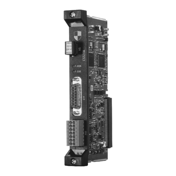
Device structure MOVISAFE® CSB31A/CSS31A MOVISAFE ® CSB31A/ CSS31A ® MOVISAFE CSB31A/CSS31A 0800 0015 DF1F 652D F-RUN F-ERR 20370612875 [1] XS: Slot for the pluggable safety key [2] "F-RUN" LED [3] "F-ERR" LED [4] X17: Connection of 2nd encoder (not used for functional safety) [5] X60: F-DIx and F-DOx connection ®... -
Page 43: Mechanical Installation
Mechanical installation Before you start Mechanical installation Before you start Observe the following information before beginning with the installation or removal of ® the MOVISAFE CS..A safety card: • Disconnect the inverter from the power. Switch off the DC 24 V and the line voltage. - Page 44 Mechanical installation Installation of the MOVISAFE® CS..A safety card MOVIDRIVE® modular 3. Remove the safety cover [1] from the front of the application inverter. 27021611749935499 4. Remove the plastic cover [1] at the card slot. 18014412495192075 INFORMATION Handling the card. ® Hold the MOVISAFE CS..A safety card only by the edges.
- Page 45 Mechanical installation Installation of the MOVISAFE® CS..A safety card MOVIDRIVE® modular ® 5. Take the MOVISAFE CS..A safety card [1] and insert it in the slot with slight pres- sure. 18014412495196939 6. Screw the safety card tight with the specified tightening torque (0.6 – 0.8 Nm). 18014412495199371 7.
-
Page 46: Installation Of The Movisafe Cs
Mechanical installation Installation of the MOVISAFE® CS..A safety card MOVIDRIVE® system/technology Installation of the MOVISAFE ® CS..A safety card MOVIDRIVE ® system/ technology ® ® Installation of the MOVISAFE CS..A safety card MOVIDRIVE system/ technology Observe the safety notes in chapter "Electrical installation" in the inverter operating in- structions. - Page 47 Mechanical installation Installation of the MOVISAFE® CS..A safety card MOVIDRIVE® system/technology INFORMATION Handling the card. ® Hold the MOVISAFE CS..A safety card only by the edges. ® 5. Take the MOVISAFE CS..A safety card [1] and insert it in the slot with slight pres- sure.
- Page 48 Mechanical installation Installation of the MOVISAFE® CS..A safety card MOVIDRIVE® system/technology 7. Install the safety cover [1] at the front of the application inverter. 14578455307 ® Manual – MOVISAFE CS..A Safety Card (Version 2)
-
Page 49: Electrical Installation
Electrical installation Important note Electrical installation Important note WARNING ® An external jumper plug X6 is plugged into the MOVIDRIVE modular/system/tech- ® nology or a voltage is connected to it, although a MOVISAFE CS..A safety card is ® installed in the MOVIDRIVE modular/system. -
Page 50: Terminal Assignment
Electrical installation Terminal assignment Terminal assignment Description LED/ Function Terminal F-RUN LED F-RUN LED The LEDs indicate the status of the CS..A safety card (see chapter "Diagnostics"). F-ERR LED F-ERR LED XS: Slot for safety key Slot for safety key X17 (D-sub DA-15): X17:1 – 15 Assignment depends on connected en-... - Page 51 Electrical installation Safe digital inputs (F-DI.) ® 2-channel signal processing of the safe digital inputs is realized in the MOVISAFE CS..A safety card. The safe digital inputs are therefore suitable for applications up to SIL 3 pursuant to IEC 61508 and Performance Level e pursuant to EN ISO 13849-1. The following external sensors to be connected and their wiring must be in compliance with the required safety class.
-
Page 52: Discrepancy Monitoring
Electrical installation Safe digital inputs (F-DI.) The assignment is made pursuant to the following table: D. Input terminal Input pair Assigned process value F-DI0 F-DI0/1 F-DI0 F-DI1 F-DI2 F-DI2/3 F-DI2 F-DI3 7.5.1 Discrepancy monitoring The safety card carries out discrepancy time monitoring for input pairs in the dual- channel equivalent and dual-channel non-equivalent connection types. -
Page 53: Signal Monitoring
Electrical installation Safe digital inputs (F-DI.) 7.5.3 Signal monitoring The signal monitoring detects when the input signal is in an undefined state (unstable state) for too long. The maximum duration for which an unstable state is permitted is calculated from the set filter time multiplied by the parameter value of the parameter Signal monitoring (Index 8704, Subindex 8). -
Page 54: Contact-Equipped Sensors (Single-Channel)
Electrical installation Safe digital inputs (F-DI.) 7.5.5 Contact-equipped sensors (single-channel) A single-channel sensor is connected via the sensor supply F-SS0 or F-SS1. The sensor cycle available there makes it possible for crossfaults in the wiring to be detec- ted. Note the detailed assignment of F-DI. to the sensor supply F-SS0 or F-SS1 in the chapter "Terminal assignment". -
Page 55: Sensors With Contact (Dual-Channel)
Electrical installation Safe digital inputs (F-DI.) WARNING ® If crossfault monitoring is deactivated, the MOVISAFE CS..A safety card cannot detect crossfaults in the cabling. This configuration is not permitted for safe applica- tions without further measures. Severe or fatal injuries. •... - Page 56 Electrical installation Safe digital inputs (F-DI.) Operation without crossfault monitoring ® When using a dual-channel, non-equivalent-switching sensor, the MOVISAFE CS..A safety card can detect a crossfault between the two digital inputs of an input pair. WARNING ® The MOVISAFE CS..A safety card cannot detect a short circuit between an F-SS. sensor supply and an associated safe digital input F-DI (jumpered sensor).
-
Page 57: Active Sensors (Dual-Channel)
Electrical installation Safe digital inputs (F-DI.) 7.5.7 Active sensors (dual-channel) When connecting a dual-channel sensor with additional voltage supply, the voltage is supplied via an external DC 24 V power supply. The voltage supplies for the sensor outputs are connected to the sensor supply F-SS0 and F-SS1. The safe outputs of the sensor are connected with 2 channels to the respective safe digital inputs (F-DI.) at terminal X60. - Page 58 Electrical installation Safe digital inputs (F-DI.) • Crossfault between a sensor supply line F-SS and a 24 V supply voltage if the di- gital input F-DI is assigned to the sensor supply and the switch contact belonging to F-DI is closed. •...
-
Page 59: Sensors With Semiconductor Outputs (Ossd, Dual-Channel)
Electrical installation Safe digital inputs (F-DI.) 7.5.8 Sensors with semiconductor outputs (OSSD, dual-channel) When connecting an OSSD-capable sensor, make sure that a pulsed voltage supply is activated for the voltage supply. INFORMATION Deactivate the crossfault monitoring at the respective safe inputs if the OSSD-cap- able sensor technology. -
Page 60: Safe Digital Outputs (F-Do.)
Electrical installation Safe digital outputs (F-DO.) Variant 2 If only OSSD sensors are used, the voltage can also be supplied via terminals F-SS0 and F-SS1. In this case, deactivate the pulsed sensor voltage supply (F-SS0 and F- SS1) in the "Assist CS.." parameterization tool. ®... -
Page 61: Capacitive Loads
Electrical installation Safe digital outputs (F-DO.) Note the dependency of the achieved Performance Level (PL) and SIL on the selected connection variant of the safe digital outputs. For each of the two outputs F-DO00 and F-DO01, a maximum switching frequency of 10 Hz is possible with a processing cycle of less than one minute. -
Page 62: Information About Line Diagnostics And Test Pulses
Electrical installation Safe digital outputs (F-DO.) 7.6.5 Information about line diagnostics and test pulses For monitoring of the cabling, the output circuit uses test pulses and thus detects faults in the external wiring. This means the output voltage is interrupted briefly (pulsed). -
Page 63: F-Do_Sto Output
Electrical installation Safe digital outputs (F-DO.) 7.6.6 F-DO_STO output The safety card has one safe output for the device-internal STO function of the in- verter. This output is electrically connected to the STO terminals of the device. This is why you must not connect anything to the external terminals. With a processing cycle of less than 1 minute, a maximum switching frequency of 10 Hz is possible. -
Page 64: Actuator (Dual-Channel, Sourcing/Sinking Output)
Electrical installation Safe digital outputs (F-DO.) 7.6.7 Actuator (dual-channel, sourcing/sinking output) ® MOVISAFE CS..A F-DO00_P F-DO00_M F-DO01_P F-DO01_M 9007207666523275 [1] Actuator Connect the actuator between F-DO._P and F-DO._M. The actuator can still be switched off in case of a crossfault in one of the connection lines, because the ®... -
Page 65: Actuator (Dual-Channel, Sourcing Output)
Electrical installation Safe digital outputs (F-DO.) 7.6.8 Actuator (dual-channel, sourcing output) In dual-channel sourcing operation, the actuators are wired as follows. MOVISAFE ® CS..A F-DO00_P F-DO00_M F-DO01_P F-DO01_M 9007207666505227 [1] Actuator Connect the actuator on two channels between F-DO00_P and GND as well as F‑DO01_P and GND. -
Page 66: Actuator (Single-Channel, Sourcing Output)
Electrical installation Safe digital outputs (F-DO.) 7.6.9 Actuator (single-channel, sourcing output) ® MOVISAFE CS..A F-DO00_P F-DO00_M F-DO01_P F-DO01_M 9007207666505227 [1] Actuator Connect the actuator between F-DO._P and the GND reference potential. The actuator input need not be isolated. The sourcing output connection variant is suitable for applications up to SIL 2 pursuant to IEC 61508 and Performance Level d pursuant to EN ISO 13849-1. -
Page 67: Built-In Encoder Ei7C Fs
Electrical installation Built-in encoder EI7C FS INFORMATION In case of a short circuit, a high short-circuit current can occur for a short time. De- pending on the DC 24 V supply voltage used, this can cause a voltage dip that limits ® ®... -
Page 68: Startup
Startup Important note Startup Important note WARNING Unexpected and unwanted movement of the drive may occur during parameteriza- tion of the safety card. Severe or fatal injuries. • Before parameterization, make sure the system is in idle state. General startup instructions INFORMATION ®... -
Page 69: Design 2: With Profisafe Connection
Startup Adjusting the maximum test duration for load with unknown capacitance Take into account the following constraints for this operating mode: ® • The parameters of the MOVISAFE CS..A safety card are set using the "Assist CS.." parameterization tool. •... -
Page 70: Parameterization Of The Drive Safety Functions
Startup Parameterization of the drive safety functions 6. Form the maximum value from the following values for the selected output: • Formed maximum value from step 4 • Value of the "Maximum duration test pulse A" display parameter (Index 8703.37) •... -
Page 71: Sto Drive Safety Function With Movisafe Cs
Startup Parameterization of the drive safety functions 5. Upload the current parameterization of the device. Once the safety key ID is entered, the current parameterization of the CS..A safety card is compared to the current parameterization in the "Assist CS.." parameteriza- tion tool. -
Page 72: Ss1(C) Drive Safety Function With Movisafe Cs
Startup Parameterization of the drive safety functions The STO/SBC drive safety function can be activated by the following sources: • F-DI (function assignment) • Safe process output data (STO 1) • SSx 1/2 final state • Fault response • Limit value violation Status The status of the STO/SBC drive safety function is displayed in the following areas: ®... -
Page 73: Ss1(A/B) Drive Safety Function With Movisafe Cs
Startup Parameterization of the drive safety functions INFORMATION If an SSx instance is assigned to another drive safety function as fault response, the SLI function cannot be parameterized as finale state. ® 8.5.5 SS1(a/b) drive safety function with MOVISAFE CS..A The SS1(a/b) drive safety function monitors the motor deceleration within defined lim- its. -
Page 74: Ss2(C) Drive Safety Function With Movisafe Cs
Startup Parameterization of the drive safety functions The value limit violation must be acknowledged. By deactivating the SSx function, the limit value violation is not acknowledged. The SSx function cannot be reactivated with an existing limit value violation. The fault can only be acknowledged if the SSx func- tion is deactivated. -
Page 75: Ss2(A/B) Drive Safety Function With Movisafe Cs
Startup Parameterization of the drive safety functions Encoder fault If an encoder fault occurs, the STO drive safety function is activated immediately without brake application delay. The status of the SSx function becomes inactive. The encoder fault must be acknowledged. The encoder fault cannot be acknowledged by deactivating the SSx function. -
Page 76: Sos Drive Safety Function With Movisafe Cs
Startup Parameterization of the drive safety functions Limit value violation Due to the value limit violation, the STO drive safety function is activated without brake application delay. The value limit violation must be acknowledged. By deactivating the SSx function, the limit value violation is not acknowledged. -
Page 77: Sla Drive Safety Function With Movisafe Cs
Startup Parameterization of the drive safety functions ® 8.5.9 SLA drive safety function with MOVISAFE CS..A INFORMATION The SLA drive safety function must not be used in combination with the EI7C FS built-in encoder. The SLA function monitors the acceleration within the parameterized limit value. The actual acceleration is monitored based on the following conditions: •... -
Page 78: Sls Drive Safety Function With Movisafe ® Cs
Startup Parameterization of the drive safety functions ® 8.5.10 SLS drive safety function with MOVISAFE CS..A The SLS drive safety function monitors the actual speed for exceeding the parameter- ized limit speed. When the limit speed is exceeded, the parameterized fault response is triggered. -
Page 79: Ssm Drive Safety Function With Movisafe Cs
Startup Parameterization of the drive safety functions When limit values are exceeded and the fault response is STO or SSx, then the fault response must be acknowledged. No acknowledgment is required if the information that limit values were exceeded is reported to a safe controller. When the speed drops below the limit value, the status of the drive safety functions is set again taking ac- count of the configured hysteresis (index 8706.57). -
Page 80: Sdi Drive Safety Function With Movisafe Cs
Startup Parameterization of the drive safety functions The SSM function is permanently active. Status If the limit values are exceeded, the status of the SSM drive safety function switches to "0". If the limit values are held again, the status of the SSM drive safety function au- tomatically switches to "1". -
Page 81: Sli Drive Safety Function With Movisafe Cs
Startup Parameterization of the drive safety functions Fault response When the limit position is exceeded, the STO drive safety function is activated without brake application delay as error response. ® 8.5.14 SLI drive safety function with MOVISAFE CS..A The SLI drive safety function can be used to realize safe, relative position functions. The SLI function monitors whether the defined limits are exceeded. -
Page 82: Encoder Fault Muting
Startup Parameterization of the drive safety functions Status The status of the SLI drive safety function is displayed in the following areas: ® • MOVISAFE CS..A diagnostics, acceleration function status • Safe process output data (SLI1, SLI2) Fault response The STO drive safety function is activated as error response in one of the following cases: •... -
Page 83: Muting Safe Process Output Data (Muting F-Po)
Startup Parameterization of the drive safety functions 8.5.16 Muting safe process output data (muting F-PO) WARNING The active function "Muting F-PO" deactivates the encoder-dependent drive safety functions (except STO). This can cause immediate startup of the system. Severe or fatal injuries. •... -
Page 84: Startup Of The Safety Card At The F-Protocol
Startup Startup of the safety card at the F-protocol Startup of the safety card at the F-protocol 8.6.1 Requirements for F-communication Requirements regarding IT security regarding F-protocols must be checked in accord- ance with EN 61508-1, chapter "Hazard and risk analysis". INFORMATION Before making changes to the set F-protocol at the CS..A safety card you have to disconnect the F-master physically. -
Page 85: Fsoe Protocol
Startup Startup of the safety card at the F-protocol PROFIsafe master settings The settings that must be made at the PROFIsafe master are shown in an example for an S71500F in the TIA portal. 28300490891 8.6.3 FSoE protocol Requirements ® •... -
Page 86: Isofast ® Protocol
Startup Startup of the safety card at the F-protocol Setting the safety protocol The CS..A safety card supports several safety protocols. For this, select "FSoE" under [F-communication] > [Configuration]. Setting the F-address The F-address must be identical to the address set for the slave in the FSoE master. Enter the correct F-address under [F-communication] >... -
Page 87: Operating States
Startup Operating states Operating states ® The MOVISAFE CS..A safety card distinguishes between the following operating states: • Operation • Parameterization • Safe state after critical error 8.7.1 Operating state "Operation" In the "Operation" operating state, the selected drive safety functions are executed in accordance with the parameterization (see chapter "Drive safety functions"). -
Page 88: Sequence
Startup Safety-relevant acceptance For unused drive safety functions, it is sufficient to verify whether the release is para- meterized to "No". 8.8.1 Sequence After a successful startup, you must confirm that the data of the acceptance report matches the parameters on the safety card. You must identify and protocol the values parameterized for the user units, sensors and monitoring functions individually by per- forming a function test. -
Page 89: Confirming Acceptance
Startup Restoring the delivery state 8.8.4 Confirming acceptance The status of the safety card must be confirmed after completion of the safety techno- logy verification. To confirm the data set, enter the checksum of the report in As- sist CS.. (line 7 in the following figure). 21877787147 Restoring the delivery state 8.9.1... -
Page 90: Reset The Password
Startup Reset the password 8.10 Reset the password 8.10.1 Procedure INFORMATION When you insert or remove the safety card, adhere to the information in chapter "Mechanical installation". Proceed as follows: 1. Switch off the system. 2. Remove the safety card. To reset the password, you require the master password of the safety card. -
Page 91: Operation
Operation Hazard caused by coasting of the drive Operation Hazard caused by coasting of the drive WARNING Hazard caused by coasting of the drive. Without mechanical brake or if the brake is faulty, a danger exists of the drive coasting to a halt. Severe or fatal injuries. -
Page 92: Data Exchange With Higher-Level Controller
Data exchange with higher-level controller Introduction Data exchange with higher-level controller 10.1 Introduction ® MOVIDRIVE devices with integrated safety card support parallel operation of stand- ard and safe communication via a bus system or network. The safe PROFIsafe com- ® munication can be carried out via PROFINET ... -
Page 93: F-Periphery-Data Component Of The Safety Card
Data exchange with higher-level controller F-periphery access of the safety card in the TIA portal 10.2.1 F-periphery-data component of the safety card While compiling the configuration tool (HW Config), the system automatically gener- ates an F periphery data component (DB) for each safety card. The F periphery DB of- fers the user an interface in which he or she can evaluate or control variables in the safety program. - Page 94 Data exchange with higher-level controller F-periphery access of the safety card in the TIA portal ACK_NEC After resolving an error, the safety card is reintegrated depending on the setting of the variable ACK_NEC. • ACK_NEC = 0: Automatic reintegration. • ACK_NEC = 1: Automatic reintegration following acknowledgment by the user. WARNING Impermissible parameterization of the variable ACK_NEC = 0.
-
Page 95: F Process Data Profile
Data exchange with higher-level controller F process data profile 10.3 F process data profile 10.3.1 CSS21A/CSS31A profile design "Technology Standard" Process output data Byte Bit Name Value Description STO1 Activate STO. Deactivate STO. SLI incre- Blockage of step motion. ment en- Release of a step. - Page 96 Data exchange with higher-level controller F process data profile Byte Bit Name Value Description SOS1 Activate SOS. Deactivate SOS. Reserve SSX1 Activate SSx1. Deactivate SSx1. SSX2 Activate SSx2. Deactivate SSx2. SDI1 Activate SDI1. Deactivate SDI1. SDI2 Activate SDI2. Deactivate SDI2. SLI1 Activate SLI1.
- Page 97 Data exchange with higher-level controller F process data profile Byte Bit Name Value Description SLA1 Activate SLA1. Deactivate SLA1. SLA2 Activate SLA2. Deactivate SLA2. Reserve Reserve Reserve Reserve Reserve Reserve 1) SBT function is not available. Process input data Byte Bit Name Value Description STO1 STO is not active.
- Page 98 Data exchange with higher-level controller F process data profile Byte Bit Name Value Description F-DI00 F‑DI00 process value: "low" or fault. F‑DI00 process value: "high". F-DI01 F‑DI01 process value: "low" or fault. F‑DI01 process value: "high". F-DI02 F‑DI02 process value: "low" or fault. F‑DI02 process value: "high".
- Page 99 Data exchange with higher-level controller F process data profile Byte Bit Name Value Description SLS1 SLS1 not active or limit violation/fault. SLS1 is active. SLS2 SLS2 not active or limit violation/fault. SLS2 is active. SLS3 SLS3 not active or limit violation/fault. SLS3 is active.
-
Page 100: Csb31A Profile Design "Technology Bus F-Do
Data exchange with higher-level controller F process data profile 10.3.2 CSB31A profile design "Technology Bus F-DO" Process output data Byte Bit Name Valu Description STO1 Activate STO. Deactivate STO. Reserve Reserve Reserve Reserve Reserve Enable F- No acknowledgment. Acknowledgment of the interlocked F-DI (0 → 1 edge). - Page 101 Data exchange with higher-level controller F process data profile Process input data Byte Bit Name Valu Description STO1 STO is not active. Safe disconnection of the drive is not active. STO signals the status "STO active". All outputs parameterized to STO are switched off. Reserve Reserve Input data...
-
Page 102: Csb21A Profile Design "Technology Bus Sto
Data exchange with higher-level controller F process data profile Byte Bit Name Valu Description Reserve Reserve SSx1 SSx1 is not active or limit violation/fault. SSx1 is active. SSx2 SSx2 is not active or limit violation/fault. SSx2 is active. Reserve Reserve Reserve Reserve Reserve... - Page 103 Data exchange with higher-level controller F process data profile Byte Bit Name Value Description Reserve Reserve Reserve Reserve Reserve Reserve Reserve Reserve Reserve Reserve SSX1 Activate SSx1. Deactivate SSx1. SSX2 Activate SSx2. Deactivate SSx2. Reserve Reserve Reserve Reserve Process input data Byte Bit Name Value Description...
-
Page 104: Process Input Data (F-Pi) Substitute Values
Data exchange with higher-level controller F process data profile Byte Bit Name Value Description F-DI00 F‑DI00 process value: "low" or fault. F‑DI00 process value: "high". F-DI01 F‑DI01 process value: "low" or fault. F‑DI01 process value: "high". F-DI02 F‑DI02 process value: "low" or fault. F‑DI02 process value: "high". -
Page 105: Process Output Data (F-Po) Substitute Values
Data exchange with higher-level controller F process data profile 10.3.5 Process output data (F-PO) substitute values In the F-controller, all bits described as "Reserve" must be set to "0". For drive safety functions that are unused, the bit must be set for the selection via the safe process output data (F-PA);... -
Page 106: Acknowledgment Of Safety Card
Data exchange with higher-level controller Acknowledgment of safety card 10.4 Acknowledgment of safety card 10.4.1 Acknowledgment of PROFIsafe data exchange The PROFIsafe communication must be error-free for safe data exchange of the safety card via PROFIsafe. As soon as there is an acknowledgment request of the safety card via the ACK_NEC bit in the F-periphery data component, the user must trigger an acknowledgment by a rising edge via the ACK_REI bit. -
Page 107: Response Times
Response times Calculation of response times Response times The response time plays a decisive role in the design and execution of drive safety functions in systems and machines. In order to match the response time to the re- quirements of a drive safety function, always take the entire system into account, from the sensor (or command device) to the actuator. -
Page 108: Encoder
Response times Calculation of response times 11.1.1 Encoder All response times must be multiplied by the factor 1,002. Calculation factor (formula Calculation specification response time symbol) sine/cosine encoder: • Processing time encoder _Sys _Task positioning _ENC_POS • Processing time encoder Filter time speed (8708.3) + T _Task _Sys... -
Page 109: Safe Communication
Response times Calculation of response times 11.1.3 Safe communication The response times for the safe communication always relate to the safe protocol and not to the external interface of the safety card. All response times must be multiplied by the factor 1,002. Calculation factor (formula symbol) Calculation specification response time Input processing time via safe process out-... - Page 110 Response times Calculation of response times Calculation factor Calculation specification response time • Via F-DI + 2 × T + brake application time (8706.15) _InputProcessing_F-DI _Sys SOS: • Via F-PA _InputProcessing_F-PA _Sys • Via F-DI _InputProcessing_F-DI _Sys SS1(b): • Via F-PA + 2 × T + SSx(b) monitoring delay t (8706.9) + brake application _InputProcessing_F-PA...
- Page 111 Response times Calculation of response times Calculation factor Calculation specification response time _InputProcessing_F-PA _Sys SSR: • Via F-PA + T + monitoring delay t (8706.53) _InputProcessing_F-PA _Sys • Via F-DI + T + monitoring delay t (8706.53) _InputProcessing_F-DI _Sys SDI: • Via F-PA + T _InputProcessing_F-PA _Sys...
-
Page 112: Response Time In Case Of Limit Value Violation In Independent Operation
Response times Calculation of response times 11.1.6 Response time in case of limit value violation in independent operation All response times must be multiplied by the factor 1,002. Calculation factor Calculation specification response time _ENC_POS _Sys SSx(b) _ENC_VEL _Sys SLS with parameter- ized error response: •... -
Page 113: Response Time In Case Of Limit Value Violation With Safe Communication
Response times Calculation of response times 11.1.7 Response time in case of limit value violation with safe communication The response times for the safe communication always relate to the safe protocol and not to the external interface of the safety card. All response times must be multiplied by the factor 1,002. -
Page 114: Deselection Of A Drive Safety Function Via A Safe Digital Input
Response times Calculation of response times Calculation factor Calculation specification response time • F-PE _ENC_ACC _Sys 1) If SBC-release (8706.14) = no, then the brake application time = 0 2) With ramp monitoring = linear, the jerk time = 0 11.1.8 Deselection of a drive safety function via a safe digital input All response times must be multiplied by the factor 1,002. -
Page 115: Service
Service Modification/changes to the device Service 12.1 Modification/changes to the device • Hardware changes Any changes to the CS..A safety card can be performed only by SEW‑EURODRIVE. • Firmware modifications Only SEW‑EURODRIVE is authorized to make changes to the firmware. •... -
Page 116: Status Leds
Service Status LEDs 12.3 Status LEDs WARNING Danger due to incorrect interpretation of the LEDs "F-RUN" and "F-ERR" Severe or fatal injuries • The LEDs are not safety-related and may not be used as a safety device. INFORMATION • "Slow" flashing frequency means that the LED is flashing at 0.5 Hz. •... -
Page 117: F-Err" Led
Service Status LEDs 12.3.2 "F-ERR" LED The following table shows the states of the "F-ERR" LED. LED status Meaning Flashing sequence Device identification for safety key ID query. Critical error, cannot be acknowledged. Red, slowly flashing • Error can be acknowledged •... -
Page 118: Error States Of The Movisafe
Service Error states of the MOVISAFE® CS..A safety card Error states of the MOVISAFE ® CS..A safety card ® 12.4 Error states of the MOVISAFE CS..A safety card DANGER ® The MOVISAFE CS..A safety card has an error and automatically restarts in the fol- lowing cases: - The DC-24-V supply voltage was switched off and back on. - Page 119 Service Error states of the MOVISAFE® CS..A safety card Input fault If the safety card detects an error at a safe digital input, the affected safe digital inputs is switched to the safe state. If the affected safe digital input is parameterized as dual- channel, both inputs are switched to the safe state.
-
Page 120: Emergency Mode" Function
Service "Emergency mode" function Error messages If there is a fault in the safety card, the inverter indicates that the safety card is report- ing a fault. Measures for error resolution and more information on causes can be found via the error status of the safety card. -
Page 121: Safety Notes
Service "Emergency mode" function 12.5.1 Safety notes DANGER Due to the "Emergency mode" function, immediate restart of the system is possible. Severe or fatal injuries. • Before activation of the "Emergency mode" function, the user must undertake or- ganizational measures for the protection of personnel and machinery. DANGER The keypad is connected to the wrong device. -
Page 122: Fault Diagnostics
Service Fault diagnostics 12.6 Fault diagnostics The "Latest initial fault" fault status shows the fault that occurred first in the safety card with the corresponding fault code, subfault code and fault description. For internal pur- poses, additional error codes are displayed. The current first error is the error that occurs after a restart or since the last acknow- ledgment as the first error with the highest priority. - Page 123 Service Fault diagnostics ® 12.6.2 Diagnostics with MOVISUITE Assist CS.. The current fault of the safety card is displayed with the corresponding fault descrip- ® tion in the "Diagnostics" segment in the menu command [MOVISAFE CS..] > [Fault status]. 21877778571 12.6.3 Diagnostics with PROFIsafe connection The CS..A safety card with PROFIsafe connection triggers a diagnostic alarm in the F- PLC in the data exchange between of F-PLC (fieldbus master) and the safety card (fieldbus slave) in case of a fault.
-
Page 124: Device Replacement
Service Device replacement 12.6.4 Fault memory The current initial fault and all other subsequent faults are residually saved in the fault memory with associated timestamp. 9007221132546955 Additional messages for the errors are entered in the fault memory in the columns "Primary error"... - Page 125 Service Device replacement ® 12.7.1 Device replacement with MOVI-C CONTROLLER The following steps must be performed for the actual device replacement: The system offers the option to save the application-related data set for the inverter and the data set for the safety card on the controller. This step must be carried out in advance by the user.
-
Page 126: Technical Data
Technical data General technical data Technical data 13.1 General technical data Value Ambient temperature for storage of the safety ≥ -25 °C – ≤ 85 °C card ® • 0 °C – 40 °C without derating Ambient temperature of MOVIDRIVE system/ technology, all sizes • 40 °C – 55 °C with derating ® (For derating, see the "MOVIDRIVE system"... -
Page 127: Encoder Interface
Technical data Encoder interface 13.3 Encoder interface Designation Value/description Features Encoder interface for HTL encoder interfaces A, A, B, B, sin/cos encoder signals Permitted safety encoders EI7C FS, AK0H, AK1H, E.7S, A.7W Signal level 0 V – +3 V Encoder track LOW (logic "0") Encoder track HIGH (logic "1") Maximum operating speed 3600 min EI7C FS, E.7S, A.7W... -
Page 128: Sensor Supply
Technical data Sensor supply 13.5 Sensor supply F-SS0, F-SS1 Value/description Properties • DC 24 V output pursuant to EN 61131-2 • Short circuit and overload protection • No galvanic isolation Rated current 150 mA Inrush current (≤ 10 ms) 300 mA Short-circuit protection 1.2 A Internal voltage drop < DC 1.3 V Pulsed voltage supply (if activated) •... -
Page 129: Characteristic Safety Values
Technical data Characteristic safety values F-DO00_P/M, F-DO01_P/M Value/description Load inductance with freewheeling ≤ 40 H diode Minimum load resistance > 130 Ω 13.7 Characteristic safety values 13.7.1 Drive safety functions without encoder evaluation Characteristic values pursuant to EN 62061/IEC 61800-5-2 EN ISO 13849-1 Tested safety class/underlying SIL 3 PL e standards Probability of dangerous failure per 4.5 × 10... -
Page 130: Movisafe ® Cs..a Safety Card (Version
Index Index Process output data ........ 95 Acknowledgment of CS..A safety card Acknowledgment of PROFIsafe data exchange Data exchange with higher-level controller .............. 106 Acknowledgment of safety card .... 106 Assist CS.. F-periphery access of the safety card in the TIA Safety concept.......... - Page 131 Index Encoder cable requirements Installation HTL encoder cable ......... 31 Safety notes ........... 13 ® SINE/COSINE encoder cable...... 30 Installation of the MOVISAFE CS..A safety card ® Encoder fault muting ........... 82 In MOVIDRIVE modular........ 43 ® Encoder requirements In MOVIDRIVE system/technology....
- Page 132 Index Preliminary information........ 11 Setup .............. 13 Response times Structure of embedded........ 9 Calculation of response times ...... 107 Structure of section-related ...... 8 General............ 107 Transport ............ 12 Restore delivery state.......... 89 ® Safety over EtherCAT Restriction of use.......... 13 Beckhoff trademark ........
- Page 133 Index General information........ 68 Operating states of the CS..A safety card .. 87 Target group ............ 11 Parameterization of the drive safety functions 70 Technical data ........... 126 Safety card at F-protocol ........ 84 Characteristic safety values ...... 129 Safety notes ........... 14 Current and power consumption of the safety Safety-relevant acceptance......
- Page 136 SEW-EURODRIVE—Driving the world SEW-EURODRIVE GmbH & Co KG Ernst-Blickle-Str. 42 76646 BRUCHSAL GERMANY Tel. +49 7251 75-0 Fax +49 7251 75-1970 sew@sew-eurodrive.com www.sew-eurodrive.com...
Need help?
Do you have a question about the MOVISAFE CS A Series and is the answer not in the manual?
Questions and answers