Federal Signal Corporation SmartSystem SS2000-LMS Installation And Maintenance Instructions Manual
Load management system, load manager with electronic siren/light control system and signalmaster directional light (with slide switch control head)
Hide thumbs
Also See for SmartSystem SS2000-LMS:
- Operation and configuration instructions (24 pages)
Table of Contents

Related Manuals for Federal Signal Corporation SmartSystem SS2000-LMS

Summary of Contents for Federal Signal Corporation SmartSystem SS2000-LMS
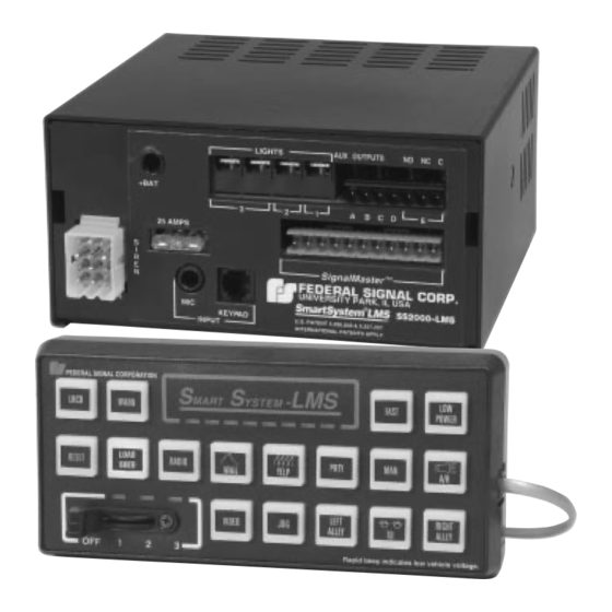
- Page 1 Price $4.00 Model SS2000-LMS SmartSystem™ Load Management System LOAD MANAGER WITH ELECTRONIC SIREN/LIGHT CONTROL SYSTEM AND SignalMaster™ DIRECTIONAL LIGHT (with Slide Switch Control Head) HARDWARE INSTALLATION AND MAINTENANCE INSTRUCTIONS...
-
Page 2: Limited Warranty
LIMITED WARRANTY The Signal Division, Federal Signal Corporation (Federal), warrants each new product to be free from defects in material and workmanship, under normal use and service, for a period of two years on parts replacement and one year on labor from the date of delivery to the first user-purchaser. - Page 3 IMPORTANT WIRING INFORMATION WARNING The SS0000-LMS is an advanced microprocessor based siren system. Unlike conventional siren systems, malfunctions and/or improper operation WILL result if proper installation procedures are not followed. Refer to the accompanying diagram and pay special attention to the "CHECK LIST" at the bottom of this page. To complete the electrical installation, refer to paragraph 3-6. IMPORTANT It is the installer's responsibility to determine an appropriate location in the vehicle circuitry to connect the PARK (NEUTRAL SAFETY) wire.
- Page 4 SECTION I GENERAL DESCRIPTION module, components. Eight relay outputs are avail- able for control of light bars, other auxiliary lights, and accessories. In addition, a full feature SignalMaster controller is integrated into the system. This system provides the automatic, simulta- neous light and siren activation required by some laws.
-
Page 5: Section Ii Specifications
SECTION II SPECIFICATIONS GENERAL. Input Voltage ............. 11VDC to 15VDC. Polarity ............Negative ground only. Operating Temperature Range ......-30°C to +65°C. Standby Current ..........Less than .5 ampere Dimensions: Amplifier/SignalMaster Control/Relay Unit Height ..........3-1/8" Width ..........6-3/8" (16.2cm) Length .......... -
Page 6: Section Iii Installation
SECTION III INSTALLATION SAFETY MESSAGE TO INSTALLERS ELECTRONIC SIRENS • Sound output will be severely reduced if any objects are WARNING in front of the speaker. If maximum sound output is The lives of people depend on your proper installation and required for your application, you should ensure that the servicing of Federal products. - Page 7 CAUTION WARNING When installing equipment inside air bag The SS2000-LMS Amplifier Unit housing equipped vehicles, the installer MUST ensure is NOT waterproof. It must be mounted in a that the equipment is installed ONLY in areas location which is sheltered from falling rain, recommended by the vehicle manufacturer.
-
Page 8: Control Head Installation
Use the mounting bracket as a template Several control head mounting methods are and scribe two drill positioning marks at the selected available. The mounting method used will depend on mounting location. available room, and user preference. CAUTION CAUTION Before drilling holes in ANY part of a vehicle, Unreliable switch activation and loss of “tactile be sure that both sides of the mounting surface feedback”... -
Page 9: Electrical Installation
12 PIN CONNECTOR CONTROL HEAD NOTE: USE ONE OF THE THREE SETS OF HOLES. THIS ALLOWS LIGHTS AUX OUTPUTS NO NC C UP/DOWN CONTROL POSITION OF THE PIVOT BRACKET. + BAT #6 SPLIT LOCKWASHER (2) A B C D E SignalMaster FUSE #6-32 x 1/4"... - Page 10 wire that was cut in step a. Insulate the splice with Park-Siren Deactivator and Load the wire nuts (supplied). Manager Activation. IMPORTANT CAUTION It is the installer's responsibility to determine The horn ring transfer circuit of the siren is an appropriate location in the vehicle cir- capable of switching a maximum of 2-amperes.
- Page 11 numbers shown are for the recommended Federal PRP. WIRE FROM SIREN 12VDC POWER CABLE, PIN 8 Signal relay. Connection to Power Source (see figure 3-6). AUXILIARY DEVICE GROUND The SS2000-LMS must operate from a 12 volt NEGATIVE ground vehicle electrical system. 290A3913-11 Therefore, before making any electrical connections, Figure 3-8.
- Page 12 The SS2000-LMS provides two terminal See figure 3-9. To protect the wire, 2 strips (TB1 & TB2) for control of light bars, auxiliary circuit breakers (CB1) rated at 50-amperes (Federal lights and accessories. A total of eight fused relay- Part No. 8474A176 or equivalent) should be con- controlled outputs are available.
- Page 13 50 AMP CIRCUIT FROM INTERFACE / RELAY TO INTERFACE / RELAY BREAKER (2) (PI-4) BLK BAT) RED, 8/10 AWG FEDERAL SIGNAL CORP. UNIVERSITY PARK, IL FUSIBLE LINK, TO NEGATIVE ( BATTERY TERMINAL FROM POSITIVE ( BATTERY TERMINAL 8 AWG, RED BATTERY LUG1 CR10...
- Page 14 CAUTION MATING CONNECTOR The unit will not operate if the telephone-type TIP OF SCREWDRIVER cable is improperly wired. If it is necessary to PRINTED CIRCUIT BOARD shorten the 4 conductor telephone-type cable, ensure that the connections made to the modular connector are exactly the same as the original cable connections.
-
Page 15: Testing After Installation
Ensure that there are no loose wire strands LEGEND INSERT (REMOVED or other bare wire which may cause a short circuit. FROM SHEET) Also, all wires must be protected from any sharp edges which could eventually cut through the insula- tion. -
Page 16: Section Iv Operation
SECTION IV OPERATION SAFETY MESSAGE TO OPERATORS OF FEDERAL SIGNAL ELECTRONIC SIRENS AND LIGHT/SOUND SYSTEMS • Although your warning system is operating WARNING properly, it may not alert everyone. People may The lives of people depend on your safe operation of not hear, see, or heed your warning signal. -
Page 17: Configuration Instructions
SECTION V CONFIGURATION CONFIGURATION INSTRUCTIONS WARNING Property damage, serious injury, or death to The SS2000-LMS is an extremely versatile load you or others may result if the SS2000-LMS is manager and configurable electronic siren and light improperly programmed. Programming, if control system. -
Page 18: Control Head
Observe the slide switch connector’s orien- tation and then disconnect the slide switch connector. Service Department Federal Signal Corporation After repair or replacement, reconnect the 2645 Federal Signal Drive green wire and slide switch connector. Ensure the University Park, IL 60466 slide switch connector is reconnected in the proper orientation—white wire toward the edge of the... - Page 19 Control Head Fuse. CAUTION To avoid damage to the unit, disconnect both A solder-in sub-miniature fuse (F1 on the red wires to the SS2000-LMS at the battery amplifier board) provides short-circuit protection for before proceeding. the control head and cable. F1 is located between K3 and IC10 (near the modular connector) on the ampli- Removal for Servicing.
-
Page 20: Replacement Parts List
6-5. REPLACEMENT PARTS LIST. Reference Description Part Number Designation Reference Description Part Number SS2000-LMS Components Designation Transformer, Output 120249 Assemblies QA, QB Transistor, Output 125468 Control Head Assy. 8572311-04 Legend Sticker Card 8572294-02 Amplifier Assy. 85361146 RJ-11 Data Cable 146863 Power Harness (12 Conductor) 175684 Fuses...
Need help?
Do you have a question about the SmartSystem SS2000-LMS and is the answer not in the manual?
Questions and answers