Table of Contents
Advertisement
Quick Links
MEB II
Installation and Programming Manual
This manual covers the MEB II Modbus Plus to Ethernet Bridge.
Effective: January 10, 2013
Niobrara Research & Development Corporation
P.O. Box 3418 Joplin, MO 64803 USA
Telephone: (800) 235-6723 or (417) 624-8918
Facsimile: (417) 624-8920
http://www.niobrara.com
MEB II Manual
Advertisement
Table of Contents

Summary of Contents for Niobrara MEB II
- Page 1 MEB II Manual MEB II Installation and Programming Manual This manual covers the MEB II Modbus Plus to Ethernet Bridge. Effective: January 10, 2013 Niobrara Research & Development Corporation P.O. Box 3418 Joplin, MO 64803 USA Telephone: (800) 235-6723 or (417) 624-8918 Facsimile: (417) 624-8920 http://www.niobrara.com...
- Page 2 Modicon, Square D, SY/MAX, Compact, Quantum, M340, Momentum, Premium are trademarks of Schneider-Electric. Subject to change without notice. © Niobrara Research & Development Corporation 2013. All Rights Reserved.
-
Page 3: Table Of Contents
Contents 1 Introduction....................9 2 Installation....................11 Device Mounting/Removal..............11 Power Supply..................12 Ethernet....................13 Setting the IP Address...............13 Setting the Subnet Mask..............14 Setting the Default Gate..............14 Ethernet Connection.................14 Modbus Plus..................17 Modbus Plus Configuration..............17 Modbus Plus Connection..............18 Modbus Plus Lights................20 Serial Ports....................21 RS-232 Ports..................21 RS-485 Ports..................23 Software Installation................25 Updating the MEBII Firmware.............26 Updating Firmware through the Web server........26... - Page 4 Modbus to SY/MAX Translations............47 SY/MAX to Modbus Translations............48 Error Translations................48 SY/MAX Serial..................49 NET-TO-NET Mode.................51 SY/MAX Ethernet.................54 SY/MAX Routing................54 PowerLogic Serial Modes..............58 6 Hot MB+ Operation..................60 Automatic Redundant Operation............60 Requirements and Restrictions............60 “Primary” Unit Configuration Procedure.........61 “Secondary” Unit Configuration Procedure........62 Example....................63 Reasons for Automatic Switchover............64 Hot MB+ Statistics and Information Registers........64 Serial Number...................66...
- Page 5 Enet Status Screen................79 MB+ Status Screen................79 App Menu.....................80 Switch Screen...................80 Info Menu....................81 MAC Address Screen...............81 Serial Number Screen...............82 Versions Screen................82 MB+ Drops Screen................82 Enet Drops Screen................83 System Menu..................84 Reboot Screen...................84 Factory Defaults Screen..............84 Password Screen................85 8 Recommended Cables................87 RS-232 Cables..................87 MM1 (PC to MEBII)................87 MM2 (Modicon PLC to MEBII)............87 MM3 (MEBII to emulate a 9-pin PC port)........88...
- Page 6 Modbus Plus Router................111 MB+ Chipset...................112 Modbus Plus Nodes................113 Module Info..................116 Config Overview................117 Register Viewer................118 Admin Menu..................119 Change Passwords................119 Configuration Backup..............120 Configuration Restore..............121 Hot Modbus Plus................122 Firmware Update................123 Reset to Factory Defaults...............124 10 MEBSW32....................125 Startup Screen..................125 Main Menu..................127 oNline Menu..................128 Edit port parameters...............129 Edit Modbus routing...............130 Auto Scan Edit................130 Global Data..................131...
- Page 7 Write setup to EEPROM..............141 Setup Menu..................142 Serial communication..............142 Terminal emulator................144 Register viewer................144 Quit Menu...................145 Contents...
-
Page 8: Introduction
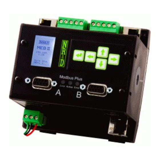
Introduction The Niobrara MEBII is a stand-alone DIN rail mount Modbus Plus to Ethernet Bridge. It features a redundant cable Modbus Plus (MB+) port, at leaset one 10/100BaseTX Ethernet port, and two isolated serial ports. The MEBII allows simultaneous pass-through routing data messages from Modbus/TCP Ethernet, MB+, and Modbus serial between all ports. - Page 9 – all from a standard browser. The MEBII also includes a “Hot MB+” mode that allows two MEBII units to work together to provide an automatic fully redundant primary/standby system for high availability systems. 10 Introduction 1 MEB II Manual...
-
Page 10: Installation
Installation WARNING: Do not connect the MEB II to any Ethernet or MB+ network before configuring the appropriate network addresses. Duplicate network address may lead to improper network communication, equipment damage, injury, or death. Device Mounting/Removal (1) Hook the top notch on the upper lip of the DIN rail. -
Page 11: Power Supply
Power Supply Connect a suitable 24VDC power to the three position removable connector. The MEB II requires a 5W minimum supply and will operate on 9-30Vdc but 24Vdc is recommended. (See Figure 2.2 Power Supply Diagram) An external fuse is recommended. -
Page 12: Ethernet
If a fixed address is required, make sure that the IP Source is set to Fixed, then select the Address page. The arrows are used to adjust the values while the arrows move between fields. The key is used to accept the new value. Figure 2.4: Fixed IP Address Screen MEB II Manual 2 Installation 13... -
Page 13: Setting The Subnet Mask
The MEBII includes a standard RJ-45 Ethernet connector with indicators for Link/Activity (green LED) and 100Mb (amber LED). (See Figure 2.7 Ethernet Port) The green Link/Activity light illuminates when the MEBII has a valid link to the attached 14 Installation 2 MEB II Manual... - Page 14 10Mb operation. The MEBII's Ethernet port supports 10/100BaseTX auto-crossover operation. Standard CAT5 cables may be used to connect the MEBII to Ethernet switches and hubs. Figure 2.7 Ethernet Port Link/ Activity Pin 1 100MB MEB II Manual 2 Installation 15...
- Page 15 “> Main > Status > Enet >” Figure 2.9: Ethernet Port Status The Ethernet port defaults to “Auto” mode but may be manually set to a fixed 10BaseT or 100BasetT with fixed Full or Half Duplex operation. 16 Installation 2 MEB II Manual...
-
Page 16: Modbus Plus
Routing Tables for the Ethernet and serial ports 1and 2 being updated to include the new drop number of the MB+ port. If No is selected, these tables will not be updated and many of the routes will not longer work properly – they must then be edited manually. MEB II Manual 2 Installation 17... -
Page 17: Modbus Plus Connection
This does not mean that the MEBII has two MB+ nodes, it behaves as a single MB+ node with two physical network connectors. The dual-cable system uses redundant wiring between nodes for added network integrity. (See Figure 2.13 Typical Dual-Cable MB+ Connection) 18 Installation 2 MEB II Manual... - Page 18 Cable A Terminator on End node Terminator on End node The MEBII may be used in a “single-cable” network by simply connecting the MB+ network to port “A”. (See Figure 2.14 Typical Single-Cable MB+ Connection) MEB II Manual 2 Installation 19...
-
Page 19: Modbus Plus Lights
The green Active light flashes in patterns to indicate the operating state of the MB+ node. (See Table 2.1: MB+ Green Active Flashes) 20 Installation 2 MEB II Manual... -
Page 20: Serial Ports
The RJ-45 connectors are used for RS-232 operation. The pin configuration is shown in Table 2.2: RJ45 RS-232 Pinout. The Niobrara MM1 cable is used to connect an one of these ports to the a standard 9-pin serial port on a PC. - Page 21 Table 2.2: RJ45 RS-232 Pinout Function No Connection DSR (pulled high) Data TX Data RX Signal GND Chassis GND 22 Installation 2 MEB II Manual...
-
Page 22: Rs-485 Ports
The pinout is shown in Figure 2.18 RS- 485 Port. Table 2.3: 5-position RS-485 pinout Function Shield No internal connection (-) data into MEBII (+) data into MEBII (-) data out from MEBII (+) data out from MEBII MEB II Manual 2 Installation 23... - Page 23 RX- RX+ Figure 2.19 Jumper for 2-wire RS-485 Shield Shield For 2-wire RS-485 operation, jumper the TX+ to RX+ to make the (+) connection, then jumper the TX- to RX- to make the (-) connection. 24 Installation 2 MEB II Manual...
-
Page 24: Software Installation
MEBII firmware files, the RPCLOAD.EXE firmware loader utility, the NRDTOOL.EXE register viewer utility, The latest version of this file is located at www.niobrara.com. Follow the link for “Download Area”, select “Module Software” and then “MEB_SETUP.EXE”. MEB II Manual... -
Page 25: Updating The Mebii Firmware
2. Click on the “Admin” link in the left green menu column. 3. Click on the “Update Firmware” link in the left green menu column. 4. Click on the “Browse” button and select the “C:\Niobrara\Firmware\MEBII.qrc” file. 5. Press the “Start Download” button to begin the update. -
Page 26: Updating Firmware Using Rpcload
1. Make sure the MEBII is powered and running. 2. Start RPCLOAD.EXE. The Windows Start Menu link is “Start, Programs, Niobrara, MEB, RPCLOAD MEBII Firmware”. 3. Click on the Browse button and select MEBII.qrc. 4. Select the Modbus TCP tab. -
Page 27: Modbus/Tcp Operation
NOTE: Index 0 has a route of NONE. The MEBII will internally process incoming Modbus/TCP messages with no route, the special index 255, or any route that doesn't leave the MEBII. This action may result in unexpected reply data since this data is from the MEB itself. MEB II Manual... - Page 28 NONE MEBII Itself MODBUS 45,5 Compact 984 PLC MODBUS 45,6,15 Quantum PLC on far side of Bridge Plus MODBUS 102,1 Power Meter 1 MODBUS 102,2 Power Meter 2 MODBUS 102,3 Power Meter 3 30 Modbus/TCP Operation 3 MEB II Manual...
-
Page 29: Default Modbus Routing Table
MODBUS MODBUS 1,63 MODBUS 1,64 MODBUS 101,1 MODBUS 101,2 MODBUS 101,3 MODBUS 101,4 MODBUS MODBUS 101,31 MODBUS 101,32 MODBUS 102,1 MODBUS 102,2 MODBUS 102,3 MODBUS 102,4 MODBUS MODBUS 102,31 MODBUS 102,32 OTHER NONE MEB II Manual 3 Modbus/TCP Operation 31... -
Page 30: Autofix Modbus Table
The Ethenet and both serial port Modbus Routing tables are examined and entries where the first drop of the route matches the old MB+ drop number are changed to match the new drop number. Figure 3.2: Edit Modbus Plus Drop 32 Modbus/TCP Operation 3 MEB II Manual... -
Page 31: Front Panel Modbus Route Edit
The Ethernet Modbus Routing tables may be modified from the front panel. The “Index” field may be changed with the UP and DOWN arrows. Pressing the ENTER button on the Index field will exit this screen. Figure 3.3: Modbus Route Edit Screen MEB II Manual 3 Modbus/TCP Operation 33... -
Page 32: Client Operation
Figure 3.5 shows an MEBII connected to a Compact 984 PLC via Modbus Plus. The Ethernet port is set to be drop 25 and is connected to a Quantum PLC at IP Address 192.168.0.24 and an M340 PLC at 192.168.0.25. 34 Modbus/TCP Operation 3 MEB II Manual... - Page 33 Server 192.168.0.24 192.168.0.25 Table 3.4: MEBII TCP Table Example Drop IP Address Downstream Comments Route 0.0.0.0 NONE 192.168.0.24 NONE Quantum PLC 192.168.0.25 NONE M340 PLC 192.168.0.205 NONE MEBII from Figure 3.1 0.0.0.0 NONE MEB II Manual 3 Modbus/TCP Operation 35...
- Page 34 IP Address to multiple table entries. Use caution with this method as there are only 64 total sockets available. There are only 8 data slave channels on the MB+ chipset in the MEBII. The drop • 36 Modbus/TCP Operation 3 MEB II Manual...
-
Page 35: Autofill Tcp Table
IP Address Route 0.0.0.0 NONE 0.0.0.0 NONE 0.0.0.0 NONE 0.0.0.0 NONE Table 3.7: Ethernet TCP Routing Table for 206.223.51.155 after AutoFill Drop IP Address Route 206.223.51.0 NONE 206.223.51.1 NONE 206.223.51.2 NONE 206.223.51.3 NONE MEB II Manual 3 Modbus/TCP Operation 37... -
Page 36: Front Panel Edit Of Tcp Table
Pressing the ENTER button while on the ZERO field will zero the IP Address. This is useful in SY/MAX Ethernet applications. Pressing the ENTER button while on the AUTO field will auto load the AutoFill value for this Index. 38 Modbus/TCP Operation 3 MEB II Manual... -
Page 37: Modbus Serial Operation
NOTE: The MEBII will internally process incoming Modbus/TCP messages with the special index 255, or any route that doesn't leave the MEBII. This action may result in unexpected reply data since this data is from the MEB itself. MEB II Manual... - Page 38 Route Comments MODBUS 45,5 Compact 984 PLC MODBUS 45,6,15 Quantum PLC on far side of Bridge Plus MODBUS 102,1 Power Meter 1 MODBUS 102,2 Power Meter 2 MODBUS 102,3 Power Meter 3 40 Modbus Serial Operation 4 MEB II Manual...
-
Page 39: Default Modbus Routing Tables
MODBUS NONE 101,4 MODBUS NONE MODBUS NONE 101,31 MODBUS NONE 101,32 MODBUS 102,1 NONE MODBUS 102,2 NONE MODBUS 102,3 NONE MODBUS 102,4 NONE MODBUS ... NONE MODBUS 102,31 NONE MODBUS 102,32 NONE MEB II Manual 4 Modbus Serial Operation 41... -
Page 40: Autofix Modbus Table
The drop number of port 2 is left at 102 (default). The normal routing to rech each meter is simply the route to reach port 2, followed by the slave address of the meter. 42 Modbus Serial Operation 4 MEB II Manual... - Page 41 Modbus/TCP message sent to the target IP device. The local M340 and Quantum NOEs don't care about the value of this number. This number is used in the Modbus Routing table in the remote MEBII to determine the target for the MSTR message. MEB II Manual 4 Modbus Serial Operation 43...
- Page 42 PLC. If multiple MB+ messages attempt to use the same data channel at the same time, the MB+ network takes care of this situation automatically, all of the messages get though, it just slows down a little as they take turns. 44 Modbus Serial Operation 4 MEB II Manual...
-
Page 43: Autofill Tcp Table
IP Address Route 0.0.0.0 NONE 10.10.10.1 NONE 10.10.10.2 NONE 10.10.10.3 NONE Table 4.5: Ethernet TCP Routing Table for 206.223.51.155 after AutoFill Drop IP Address Route 0.0.0.0 NONE 206.223.51.1 NONE 206.223.51.2 NONE 206.223.51.3 NONE MEB II Manual 4 Modbus Serial Operation 45... -
Page 44: Legacy Sy/Max Operation
Modbus 3x data (read only). The mapping is just like 4x registers and is simply the target SY/MAX address. Coils (0x) - Modbus coils (read/write) may be mapped into SY/MAX registers. • The translation starts as SY/MAX register 1, bit 1 (S1-1) = Modbus coil 0x1. S1- MEB II Manual... -
Page 45: Sy/Max To Modbus Translations
Individual servers may have additional register count restrictions. Error Translations Modbus and SY/MAX do not share the same error messages. Table 5.1 shows the MEBII's translations. All other errors are passed straight through with no translation. 48 Legacy SY/MAX Operation 5 MEB II Manual... -
Page 46: Sy/Max Serial
Ethernet Port. The type set to OTHER since this is not a MODBUS target. A Modbus/TCP client such as the M340 PLC in this example would simply use Modbus/TCP index 1 to access the SY/MAX PLC. MEB II Manual 5 Legacy SY/MAX Operation 49... - Page 47 The route to the Compact would be 101,5,6 while the route to the M340 would be 101,0,25,1 assuming that the Ethernet port on the MEBII is set to 0 and TCP table entry 25 has the IP Address of the M340. 50 Legacy SY/MAX Operation 5 MEB II Manual...
-
Page 48: Net-To-Net Mode
The MEBII may be connected to a SY/NET network using the NET-TO-NET mode. This mode is used to connect the MEBII to an RS-422 port on a CRM-510 NIM, RS-422 port on a SY/LINK (SFI-510) PC card, Niobrara SPE4, EPE5, or even MEB modules. The following rules apply to NET-TO-NET ports: Both ports must be set to NET-TO-NET mode. - Page 49 Most NIMs use BCC but the CRM-511 and 512 may be set to use CRC-16. The route message includes the NET-TO-NET drop number only once for the port pair. Figure 5.2 NET-TO-NET Serial Routing Example MB+ 5 Drop 117 MU7 Cable MB+ 6 192.168.0.241 192.168.0.25 52 Legacy SY/MAX Operation 5 MEB II Manual...
- Page 50 MEBII port 1 connected to the NIM. The MEBII takes care of changing the 1 to 117 before it leaves the device. Any of the SY/MAX PLCs may access devices through the MEBII with TREAD or TWRITE messages. MEB II Manual 5 Legacy SY/MAX Operation 53...
-
Page 51: Sy/Max Ethernet
The SY/MAX 802.3 protocol supports up to 100 physical node addresses (0-99). Logical Node numbers 100-199 are possible on Niobrara devices (MEB, EPE5, RPC) by setting a serial or MB+ port to “On Ethernet YES”. Node numbers above 100 also consume the node modulo 100. - Page 52 Figure 5.3 SY/MAX Ethernet Routing Example MB+ 5 MB+ 6 192.168.0.241 SY/MAX Drop 21 192.168.0.25 Media Converter M650 EPE5 Drop 22 Drop 112 M450 Drop 24 EPE5 ThinWire M400 Drop 23 Ethernet MEB II Manual 5 Legacy SY/MAX Operation 55...
- Page 53 Ethernet port. The drop following the second entry is the TCP Table entry of the M340 PLC. The MEBII uses the entry in the TCP routing table to decide to send the message out as Modbus/TCP (entry not 0.0.0.0) or SY/MAX 802.3 (entry is 0.0.0.0). 56 Legacy SY/MAX Operation 5 MEB II Manual...
- Page 54 Index Type Route Comments OTHER NONE MODBUS MODBUS MODBUS MODBUS MODBUS MODBUS Compact 984 PLC MODBUS MODBUS 5,21 OTHER 21,22 Model 650 OTHER 21,23,112 Model 400 OTHER 21,24 Model 450 MODBUS 5,25 MEB II Manual 5 Legacy SY/MAX Operation 57...
-
Page 55: Powerlogic Serial Modes
Note that some PowerLogic devices only support 4-wire RS-485, some only support 2- wire RS-485, and some may be used in either mode. Note that some PowerLogic devices only support EVEN parity, some only support NONE, and some support both settings.aa 58 Legacy SY/MAX Operation 5 MEB II Manual... - Page 56 NONE 2-wire EVEN BCPM Modbus 4-wire NONE 2-wire EVEN PowerLink PLOGIC 4-wire EVEN Must cycle power when changing PNIM only between PNIM and PLOGIC PowerLink Modbus 4-wire NONE 2-wire EVEN Modbus ASCII MEB II Manual 5 Legacy SY/MAX Operation 59...
-
Page 57: Hot Mb+ Operation
The transition from Secondary to Primary is not “bumpless”. It takes about 16 • seconds for the Modbus Plus chipset to restart to the Primary's address. SY/MAX 802.3 Ethernet operation is not supported in Hot MB+ mode at this • time. 60 Hot MB+ Operation 6 MEB II Manual... -
Page 58: Primary" Unit Configuration Procedure
If configuring through the web server: Select “Config”, “Port 2”, and change the mode to “Hot MB+”. Now select “Init Primary” then “Store EEPROM”. The “Primary” unit is now fully functional. MEB II Manual 6 Hot MB+ Operation 61... -
Page 59: Secondary" Unit Configuration Procedure
8. When the Secondary unit is finished fetching the configuration from the Primary, it reboots and assumes normal Hot MB+ operation. 9. Now connect the Ethernet and MB+ cables. The IP Address should be Primary+1. 62 Hot MB+ Operation 6 MEB II Manual... -
Page 60: Example
Example Figure 6.1 Hot MB+ Example Port 2 4-wire RS-422 Cable To MB+ Network MEB II Manual 6 Hot MB+ Operation 63... -
Page 61: Reasons For Automatic Switchover
It may be desirable to have an HMI periodically poll the Primary MEBII to read the state of the Primary and Secondary units. The serial number of the primary unit may also be 64 Hot MB+ Operation 6 MEB II Manual... - Page 62 12. To calculate the S/N, multiply this value by 65536 and then add the value from register 2137. (12 x 65536) + 13679 = 800111 Table 6.1: Hot MB+ Statistics MEB II Manual 6 Hot MB+ Operation 65...
-
Page 63: Serial Number
This command will only take effect if the Primary “sees” the Secondary as being online and fully functional as a standby unit. If the Primary thinks the Secondary is not able to take over as primary, this command is ignored. 66 Hot MB+ Operation 6 MEB II Manual... -
Page 64: Front Panel Operation
IP Address, duplicate SY/MAX 802.3 node, or the various Modbus Plus status descriptions are shown. Certain errors will flash the backlight until a key is pressed to draw attention to the MEBII. MEB II Manual 7 Front Panel Operation 67... -
Page 65: Main Menu Screen
Selecting the Config item leads to the Config menu and a choice of Comms and Display. The Comms sub-menu moves on to Ethernet, serial port, and MB+ options while the Display sub-menu allows the user to adjust the screen contrast. 68 Front Panel Operation 7 MEB II Manual... -
Page 66: Comms Menu Screen
The Ethernet menu allows the selection of editing the settings for the IP Address, Subnet Mask, Default Gateway, IP Source, Ethernet Protocol, port drop number, Modbus Routes, IP Route table, and the physical Ethernet port mode settings. MEB II Manual 7 Front Panel Operation 69... -
Page 67: Ip Addr Screen
ENTER key and a prompt for “Auto Set Default Gate?” is presented. Select “Yes” to have the MEBII automatically apply the subnet mask to the IP Address to generate most of the default gateway setting.. 70 Front Panel Operation 7 MEB II Manual... -
Page 68: Default Gate Screen
The IP Source screen allows the user to configure the appropriate setting. Use the UP and DOWN buttons to select the setting. DHCP and BOOTP typically require the server to be configured for the MAC address of the MEBII's Ethernet port. MEB II Manual 7 Front Panel Operation 71... -
Page 69: Ethernet Protocol Screen
The drop number of the Ethernet port defaults to 0 and rarely needs to be changed. This drop number is used to set the SY/MAX 802.3 Ethernet node number when the Ethernet port is set to MB+SYMAX protocol mode. 72 Front Panel Operation 7 MEB II Manual... -
Page 70: Modbus Route Screen
Up/Down to edit Route Up/Down to change, *** to delete element Enter to exit screen Modbus for Modbus Target Enter on “TEST” to OTHER for SY/MAX generate test message Figure 7.12:Modbus Route Edit Screen MEB II Manual 7 Front Panel Operation 73... -
Page 71: Ip Route Screen
The enter button exits the screen when on the index field. The enter button on the ZERO field causes the IP Address to be set to 0.0.0.0. This is handy for zeroing an entry for SY/MAX 802.3 Ethernet entries. 74 Front Panel Operation 7 MEB II Manual... -
Page 72: Ethernet Mode Screen
The possible settings are: AUTO • 10BaseT – Full Duplex • 10BaseT – Half Duplex • 100BaseT – Full Duplex • 100BaseT – Half Duplex • Figure 7.15:Ethernet Port Mode Screens MEB II Manual 7 Front Panel Operation 75... -
Page 73: Serial Port Menu
Chevron (combination Modbus RTU master with RNIM master) ◦ Dual Slave (combination Modbus RTU slave and SY/MAX slave) ◦ Hot Modbus Plus (Port 2 only) ◦ SY/MAX, NET-TO-NET, RNIM Master, RNIM Slave (legacy Square D PLC ◦ 76 Front Panel Operation 7 MEB II Manual... -
Page 74: Modbus Plus Edit Screen
◦ Peripheral, Share, Transfer (legacy Square D ASCII) ◦ Gateway (legacy Niobrara ASCII) ◦ Multidrop (legacy Niobrara serial network) ◦ Baud Rate – 50, 75, 110, 134.5, 150, 300, 600, 1200, 1800, 2400, 4800, 7200, • 9600 (default), 19200 Parity – EVEN (default), ODD, NONE •... -
Page 75: Display Edit Screen
Each port has multiple screens to give statistical counters about communication through the port. LEFT and RIGHT arrows change between ports. UP and DOWN move between pages for a given port. ENTER returns to the previous menu. 78 Front Panel Operation 7 MEB II Manual... -
Page 76: Enet Status Screen
The Enet status screen shows the current physical connection status of the Ethernet port. Figure 7.22: Status Menu Screen MB+ Status Screen The MB+ status screen shows information about the state of the MB+ port. Figure 7.23: Status Menu Screen MEB II Manual 7 Front Panel Operation 79... -
Page 77: App Menu
App Menu The APP menu allows the user to halt the MEBII application. This feature should only be used when directed by Niobrara Technical Support. Figure 7.24: App Menu Screen Switch Screen The Switch screen allows the user to HALT or RUN the MEBII application. The MEM PROT setting is ignored at this time and is the same as RUN. -
Page 78: Info Menu
The MAC address screen shows the hardware address of the Ethernet port in hexadecimal. This information is useful when the IP Address is set by BOOTP or DHCP. Figure 7.27: MAC Address Screen MEB II Manual 7 Front Panel Operation 81... -
Page 79: Serial Number Screen
MEBII. This page is dynamically updated and may stretch to show more than one screen. The UP and DOWN keys may be used to move between screens if needed. The MB+ node of the MEBII is highlighted. 82 Front Panel Operation 7 MEB II Manual... -
Page 80: Enet Drops Screen
Any drop numbers local the MEBII are highlighted. This includes the Ethernet port and any other port with “ON ETHERNET” set to YES. Figure 7.31: SY/MAX Ethernet Drops Screen MEB II Manual 7 Front Panel Operation 83... -
Page 81: System Menu
The Factory screen allows the user to quickly reset the MEBII to factory defaults. The reset process also includes a reboot. Selecting “NO” will return to the previous menu without altering the current setup. Figure 7.33: Factory Defaults Screen 84 Front Panel Operation 7 MEB II Manual... -
Page 82: Password Screen
(0000-9999) that must be entered before settings are altered. Once the password is entered, it settings may be altered until a reboot or the backlight timeout occurs. Setting the password to 0000 disables the feature. Figure 7.34: Password Screen MEB II Manual 7 Front Panel Operation 85... -
Page 83: Recommended Cables
RS-232 Cables MM1 (PC to MEBII) The Niobrara MM1 cable may be used to connect the MEBII RS-232 port to a standard PC 9-pin male port. The pinout is shown in Figure 8.1.: MM1 Serial Cable. Figure 8.1.: MM1 Serial Cable... -
Page 84: Mm3 (Mebii To Emulate A 9-Pin Pc Port)
MM3 (MEBII to emulate a 9-pin PC port) The Niobrara MM3 cable may be used to make the MEBII RS-232 port appear as a standard PC 9-pin male port. This cable is often used along with an MM1 cable to connect two RJ-485 RS-232 ports together such as an MEBII to a newer Compact 984 PLC. -
Page 85: Rs-485 Cables
RS-485 Cables MU7 (MEBII to SY/MAX) The Niobrara MU7 cable is used to connect the RS-485 port of the MEBII to a standard SY/MAX DB9 female port. This cable is normally used to connect the MEBI directly to a SY/MAX PLC or NIM module. -
Page 86: Mebii To 2-Wire Rs-485
The shield wire should only be grounded at one location - usually at the master. A simple method of grounding the shield is to connect the Shield terminal of the MEB's RS-485 connector to the Earth Ground terminal of the MEBII's power supply connector. 90 Recommended Cables 8 MEB II Manual... - Page 87 TX(+) RX(+) RX(+) RX(-) TX(-) RX(-) RX(-) RX(+) RX(-) Shield Shield Shield Shield Terminator on last Driver Mode: Bias on some slave, Terminator on last slave RS485-Bias could be same as slave terminator MEB II Manual 8 Recommended Cables 91...
-
Page 88: Web Server
MEBII. If the “User” account is used and the operator attempts to modify a setting in the MEBII, a pop-up notification will appear to announce that modifications are not allowed for this user level. (See Figure 9.2) MEB II Manual... - Page 89 Figure 9.1: Login Screen Figure 9.2 “User” attempting to modify settings 94 Web Server 9 MEB II Manual...
-
Page 90: Home
The Configuration menu provides access to the settings for Ethernet, Port 1, Port 2, and Modbus Plus. Ethernet There are pages for setting the IP Address, Ethernet Protocol, Modbus Routing, TCP Client Routing, and I/O Scanner. MEB II Manual 9 Web Server 95... -
Page 91: Ip Settings
IP Settings The IP Settings page allows the Admin to select the IP Parameters for the module. 96 Web Server 9 MEB II Manual... -
Page 92: Ethernet Port Parameters
Ethernet Port Parameters This page allows the Admin to configure the MEBII to operate in Modbus/TCP or SY/AMX+Modbus/TCP mode and set the SY/MAX 802.3 drop number. MEB II Manual 9 Web Server 97... -
Page 93: Modbus Routing For Ethernet Port
NOTE: Using the Ethernet port's drop number as the first drop in the route will cause the message to be routed back out the Ethernet port. This feature allows the MEBII to translate between Modbus/TCP and SY/MAX 802.3 Ethernet. 98 Web Server 9 MEB II Manual... -
Page 94: Tcp Routing Table
TCP Routing Table The TCP Routing table is used for Modbus/TCP Client operation. NOTE: SY/MAX 802.3 Ethernet client operation is selected by setting the drop number IP Address to 0.0.0.0. MEB II Manual 9 Web Server 99... -
Page 95: I/O Scanner
Write, and Read+Write time based messages to be generated between the MEBII and up to 128 Modbus TCP servers. The I/O Scanner operates on the Mailbox registers (1-2048) in the MEBII's internal registers. 100 Web Server 9 MEB II Manual... -
Page 96: Serial Ports
Changing the protocol mode will prompt the “Admin” to “Apply typical settings” for the new mode. Selecting “OK” will change many of the settings to match the normal usage of the new mode. MEB II Manual 9 Web Server 101... -
Page 97: Serial Port Modbus Routing Table
Serial Port Modbus Routing Table Each serial port includes its own 254 entry look-up table for Modbus Slave operation. The first drop in the Route field is the drop number of the outbound MEBII port. 102 Web Server 9 MEB II Manual... -
Page 98: Serial Port Auto Scan
NOTE: The Auto Scan Table for port 2 is disable when the MEBII is in Hot Modbus Plus operation. NOTE: Port 2 Auto Scan may be used to generate read/write messages onto MB+ by entering the MB+ port drop number as the first entry in the Route field. MEB II Manual 9 Web Server 103... -
Page 99: Modbus Plus Port Parameters
Modbus Plus Port Parameters The MB+ port settings may be altered on this page. 104 Web Server 9 MEB II Manual... -
Page 100: Modbus Plus Global Data
MB+ network. The subscription data will be placed in the mailbox registers of the MEBII. NOTE: Hot Modbus Plus operation uses the Global Data output and is thus not available for customer use. MEB II Manual 9 Web Server 105... - Page 101 106 Web Server 9 MEB II Manual...
-
Page 102: Statistics
NOTE: These counters do not survive a power cycle/reboot. Ethernet Router Stats The Ethernet Router page shows counters for the SY/MAX / Modbus router for this port. MEB II Manual 9 Web Server 107... -
Page 103: Sy/Max 802.3 Ethernet Nodes
100 and configured for “ON Ethernet YES” will also consume the SY/MAX drop number minus 100. Drop Number of peer devices are highlighted in blue. 108 Web Server 9 MEB II Manual... -
Page 104: Serial Port
Serial Port Serial ports 1 and 2 have counter pages to show the SY/MAX / Modbus router information associated with that port. MEB II Manual 9 Web Server 109... -
Page 105: Port 2 Hot Modbus Statistics
Port 2 Hot Modbus Statistics The statistics page for Port 2 is different when the MEBII is configured for Hot Modbus Plus operation. 110 Web Server 9 MEB II Manual... -
Page 106: Modbus Plus Router
Modbus Plus Router The Router statistics page shows the normal SY/MAX / Modbus router counters for the MB+ port. MEB II Manual 9 Web Server 111... -
Page 107: Mb+ Chipset
MB+ Chipset The MB+ Chipset page shows information provided by the MB+ chipset. These counters are not resettable. 112 Web Server 9 MEB II Manual... -
Page 108: Modbus Plus Nodes
Modbus Plus Nodes This table shows all possible 64 MB+ stations on the MEBII's local MB+ network. The MEBII's drop number is highlighted in green. All other visible nodes are highlighted in blue. MEB II Manual 9 Web Server 113... - Page 109 114 Web Server 9 MEB II Manual...
- Page 110 MEB II Manual 9 Web Server 115...
-
Page 111: Module Info
Module Info The Module Info page shows the MEBII's serial number and various firmware versions. 116 Web Server 9 MEB II Manual... -
Page 112: Config Overview
MEBII. This page may be printed to provide a hard copy of the module's setup. Note: This page takes several seconds to populate. At the end of the configuration is a text line “This is the end of the Configuration Listing.” MEB II Manual 9 Web Server 117... -
Page 113: Register Viewer
Multiple viewing windows may be opened. Windows may be closed by clicking the “X” in the upper left corner of the window. The polling rate of each viewing window is adjustable with the pull-down in the upper corner of each window. 118 Web Server 9 MEB II Manual... -
Page 114: Admin Menu
The Admin menu heading is only shown when the “Admin” account is used for the web login. Change Passwords The Change Password page allows the Administrator to modify the “Admin” and/or “User” passwords. MEB II Manual 9 Web Server 119... -
Page 115: Configuration Backup
PC. The common method is to right click the “here” link and choose “Save Link As...” or “Save Target As...” and then save the file. The default filename is of the form: config_192_168_1_14.mebii where 192.168.1.14 is the IP Address of the MEB in question. 120 Web Server 9 MEB II Manual... -
Page 116: Configuration Restore
Configuration Restore The Restore link will allow the Admin to restore a previously saved backup file to the MEBII. MEB II Manual 9 Web Server 121... -
Page 117: Hot Modbus Plus
Hot Modbus Plus The Hot Modbus Plus page may be used to initialize the MEBII as the first Primary or Secondary unit. 122 Web Server 9 MEB II Manual... -
Page 118: Firmware Update
The Firmware Update page allows the Admin to install a new version of the MEBII.qrc file. NOTE: It is always recommended that a new backup of the MEBII configuration be done before updating the firmware. The new firmware is usually installed in the c:\Niobrara\Firmware\ folder. MEB II Manual 9 Web Server 123... -
Page 119: Reset To Factory Defaults
Address, Subnet Mask, and Default Gateway) but will revert all other settings to factory default. NOTE: Resetting the MEBII to Factory Default using the front panel LCD will also revert the IP settings to 10.10.10.10. 124 Web Server 9 MEB II Manual... -
Page 120: Mebsw32
MEBII and older MEB hardware. Startup Screen Figure 10.1: Startup Screen The fist time that MEBSW32 is started, it will show a screen like Figure 10.1. The date in the upper right corner (06Aug2010) is the revision of MEBSW32. The Error MEB II Manual... - Page 121 255. See section Serial communication on page 142 for more information. Pressing “Enter” after selecting the Index field will pop up the “Write setup to startup file?” window. Pressing “Enter” or “y” will save the file and avoid the error on the next startup. 126 MEBSW32 10 MEB II Manual...
-
Page 122: Main Menu
“F” for oFfline – Edit, Save, Print offline copies of the MEBII's configuration. • “U” for Utility – View registers, statistics, MB+ station lists. • “S” for Setup – Configure the PC connection. • “Q” for Quit – Exit the MEBSW32 program. • MEB II Manual 10 MEBSW32 127... -
Page 123: Online Menu
Auto scan table – Configure the automatic polling tables for the serial and • MB+ ports. edit Global data table – Modify the MB+ Global Data Table. • edit TCP routing – Modify the Modbus/TCP client IP Address table. • 128 MEBSW32 10 MEB II Manual... -
Page 124: Edit Port Parameters
The oNline edit port parameters screen has a column for the Ethernet port, each serial port, and the MB+ port. The arrow keys are used to move the highlighted cell around. The space bar and + and – keys are used to modify the values. MEB II Manual 10 MEBSW32 129... -
Page 125: Edit Modbus Routing
Auto Scan Edit The Auto Scan feature allows a serial port to automatically generate up to 48 sequential messages on a fixed time interval. The messages may be either a read or a write. Each 130 MEBSW32 10 MEB II Manual... -
Page 126: Global Data
The REG field is the MEBII's mailbox register and must be within the range of 1-2048. The COUNT field is set to 0 to disable the subscription and has a maximum value of 32. MEB II Manual 10 MEBSW32 131... -
Page 127: Tcp Routing
The Auto-Fill feature of the IP table on the MEBII's front panel will automatically place the first three octets of the new IP Address in each of the 200 entires of this table. The fourth octet will simply be the index value for the entry. 132 MEBSW32 10 MEB II Manual... -
Page 128: Offline Menu
Figure 10.10: TCP Routing Screen offline Menu The oFfline menu allows MEBII configuration without a physical connection to the hardware. Figure 10.11: TCP Routing Screen MEB II Manual 10 MEBSW32 133... -
Page 129: Read From Disk To Memory
PC. The navigation and file name operation is the same as the “Read from disk to memory”. Edit configuration in memory The oFfline, Edit configuration in memory screen works just like the oNline Edit port parameters version on page 129. 134 MEBSW32 10 MEB II Manual... -
Page 130: Edit Modbus Routing
Copy offline to module flash This menu item is to supported by the MEBII. It is only used with the older SY/MAX versions of the MEB. MEB II Manual 10 MEBSW32 135... -
Page 131: Quit Offline Functions
Use the number keys to modify the register's content. Pressing Enter will send the new data to the target. NOTE: Writing data to a target device may cause unexpected behavior, equipment damage, personal injury or death. 136 MEBSW32 10 MEB II Manual... -
Page 132: View Module Revision
Jump to a particular register location by typing in a new number while the cursor is in the far left column. Figure 10.14: Utility Menu Screen view module Revision The view module Revision screen will show the MEBII's current firmware revision. Figure 10.15: Utility View Module Revision Screen MEB II Manual 10 MEBSW32 137... -
Page 133: View Statistics
Pressing the + and – or “space bar” buttons will move between port pages. Use the “z” or “0” key s to zero the counters for a given port. Figure 10.16: Ethernet Statistics Screen Figure 10.17: MB+ Statistics Screen 138 MEBSW32 10 MEB II Manual... -
Page 134: Terminal Emulator
This screen shows the state of the Clear To Send line of the RS-232 ports on the MEBII. NOTE: the port needs to be in RS-232 mode for this value to make sense. Figure 10.18: CTS Monitor Screen MEB II Manual 10 MEBSW32 139... -
Page 135: Modbus+ Station List
SY/MAX 802.3 devices. Press the F2 key to generate a new global poll. Nodes that are in the MEBII are inverted. Note, this may include serial and MB+ ports set to “On Etherent = YES”. 140 MEBSW32 10 MEB II Manual... -
Page 136: Download Firmware To Module
Select this menu item to store the current settings to EEPROM. NOTE: This operation is required when values are changed using this software. Otherwise the new settings will be lost on a power cycle. MEB II Manual 10 MEBSW32 141... -
Page 137: Setup Menu
A typical SY/MAX serial direct connection to an MEBII port in SY/MAX mode will be at 9600,EVEN,8,1 with a route of NONE. A typical Net-to-Net connection will be at 9600,EVEN,8,1 with a route of the drop number of the Net-to-Net port. 142 MEBSW32 10 MEB II Manual... - Page 138 Figure 10.22: Setup Serial Screen for Modbus/TCP connection Figure 10.23: Setup Serial Screen for Modbus RTU connection MEB II Manual 10 MEBSW32 143...
-
Page 139: Terminal Emulator
Starting Register – defaults to 1 • Register Set – 4x = Modbus Holding Registers, 3x = Modbus Analog Inputs • Identify Module – Poll register 8188 and show the value at the top of the screen • 144 MEBSW32 10 MEB II Manual... -
Page 140: Quit Menu
Figure 10.25: Setup Register Viewer Quit Menu Press Enter to exit the MEBSW32 program. MEB II Manual 10 MEBSW32 145...
Need help?
Do you have a question about the MEB II and is the answer not in the manual?
Questions and answers