Table of Contents
Advertisement
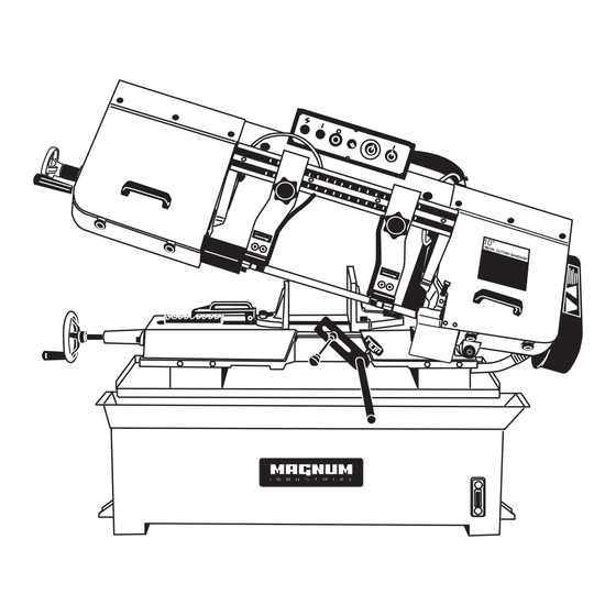
MODEL NO.: MI-93500
SPECIFICATIONS
Speeds: 60Hz 82, 132, 170, 235FPM
Motor:
60Hz 2HP 1725RPM 1PHASE
Capacity: 90°● 250MM ▄ 250x415MM
90°● 10"
45°● 190MM ▌250x190MM
45°● 7-1/2"
▄ 200x450MM
▄ 10"x16-1/2"
▄ 8"x18"
▌10"x7-1/2"
Blade:
27MMx0.9MMx3300MM
(1"x0.032"x130")
Dimension:
L:1730MMxW:760MM
(L68"xW30")
Blade Wheels:
355MM (14") Diameter
Shipping Weight: 320KGS/360KGS
Advertisement
Table of Contents

Related Manuals for Magnum Industrial MI-93500

Summary of Contents for Magnum Industrial MI-93500
- Page 1 MODEL NO.: MI-93500 SPECIFICATIONS Speeds: 60Hz 82, 132, 170, 235FPM Blade: 27MMx0.9MMx3300MM (1″x0.032″x130″) Motor: 60Hz 2HP 1725RPM 1PHASE Dimension: L:1730MMxW:760MM (L68″xW30″) Capacity: 90°● 250MM ▄ 250x415MM ▄ 200x450MM Blade Wheels: 355MM (14″) Diameter 90°● 10″ ▄ 10″x16-1/2″ ▄ 8″x18″ Shipping Weight: 320KGS/360KGS 45°●...
- Page 2 WARNING For Your Own Safety Read Instruction Manual Before Operating Saw a) Wear eye protection. b) Do not remove jammed cutoff pieces until blade has stopped. c) Maintain proper adjustment of blade tension, blade guides, and thrust bearings. d) Adjust upper guide to just clear workpiece. e) Hold workpiece firmly against table.
- Page 3 ELECTRICAL CONNECTION/DISCONNECTION. FOR 3 PHASE 1. Electrical connection: a. A cable with four wires is equipped to connect your machine into the 3 phase power supply. Please connect your machine into the power supply with hand-operated disconnecting device, which is in compliance with subclause 5.3 of EN 60204, such as no fuse breaker or plug/socket combination.
-
Page 7: Transportation Methods
Transportation Methods ! WARNING Always keep balance of the machine in transportation. Watch the gravity ! Drive folk lift slowly and carefully. -
Page 8: Blade Selection
Operating Instructions THE SELECTION OF SAWBLADES Cutting Material Check Coolant: Low coolant level causes foaming and high blade temperatures. Dirty or <3mm >5mm >50mm >100mm >150mm >200mm weak coolant can clog pump, causes crooked Sawblade <0.12” >0.2” >2” >4” >6” >8”... -
Page 9: Single Phase
Single Phase Refer to the wire drawing inside the electrical box and above for proper motor and transformer connections, lead selection and wiring connections from the motor to the power source for the voltage you are using. Three Phase Refer to the wire drawing inside the electrical box and above for proper motor and transformer connections, lead selection and wiring connections from the motor to the power source for the voltage you are using. -
Page 10: Starting And Stopping The Machine
9. Work the blade all the way up between the blade guide bearings with the back of the blade against the back-up bearing, as shown in Fig.2. Note: If bearings need adjustment, refer to the section adjusting blade guide roller bearings. -
Page 11: Blade Tracking Adjustment
Blade Tracking Adjustment Blade tracking has been set at the factory and should require no adjustment. If a tracking problem occurs, adjust the machine as follows: Since tracking can only be adjusted while machine is running, it is suggested that this adjustment be accomplished by qualified personnel that are familiar with this type of adjustment and the dangers associated with it. - Page 12 Adjusting Blade Guide Brackets The blade guides should be set as close to the vise jaws as possible. The right blade guide bracket, is not adjustable and is set at the factory to clear the right hand vise jaw. The left blade guide bracket can be moved to the left or right depending on the size of the workpiece.
-
Page 13: Vise Adjustment
Vise Adjustment To position the moveable vise jaw: 1. Turn vise handwheel (A – Fig.10) 1/2 turn counter-clockwise. 2. Move rack block (B – Fig.10) to desired location by sliding along the bed. Place the rack block onto the rack. 3. -
Page 14: Changing Speeds
Changing Speeds For 250A Your machine is provided with four speeds. To change speeds, proceed as follows: 1. Disconnect the machine from the power source. 2. Loosen wing nut (A), Fig.12 and lift up and swing belt and pulley guard (B) to the side of the machine. - Page 15 PARTS LIST FOR MI-93500 PARTS # DESCRIPTION SPECIFICATION PARTS # DESCRIPTION SPECIFICATION MI-93500-1 MI-93500-52 n i l MI-93500-1-1 MI-93500-52-1 MI-93500-1-2 MI-93500-53 c i l MI-93500-2 Hex. Cap Bolt M12x65 MI-93500-53-1 Lock Washer MI-93500-3 MI-93500-53-2 MI-93500-4 MI-93500-54 MI-93500-5 MI-93500-55 MI-93500-6 MI-93500-56...
- Page 16 PARTS LIST FOR MI-93500 PARTS # DESCRIPTION SPECIFICATION PARTS # DESCRIPTION SPECIFICATION MI-93500-102-2 MI-93500-159 Set Screw M6x8 MI-93500-103 Hex. Cap Bolt M12x35 MI-93500-160 Adjusting Valve Motor Mount Bracket MI-93500-104 MI-93500-160-1 Brace MI-93500-105 Column MI-93500-160-2 Lock Washer Hex. Socket Cap Screw...
Need help?
Do you have a question about the MI-93500 and is the answer not in the manual?
Questions and answers