
Summary of Contents for CSM XCP-Gateway
- Page 1 XCP-Gateway User Guide Version 01.00 Innovative Measurement and Data Technology...
- Page 3 All trademarks being mentioned in this document are properties of their respective owners. Contact Information CSM offers support for its products during the entire product lifecycle. Updates for all components (e.g. documentation and configuration software) will be provided on the CSM website as soon as they become available.
- Page 4 XCP-Gateway User Guide Version 01.00 User Guide...
-
Page 5: Table Of Contents
Indicator LEDs “PC” and “ECAT” ............... 7 3.1.2.2 Status-LEDs “Gateway” and “Bus” ............. 7 MOUNTING AND INSTALLATION ..............9 Before mounting the device ....................9 Mounting XCP-Gateway ....................10 Installing XCP-Gateway ..................... 11 4.3.1 Before installing the device ..................11 4.3.2 Connectors ...................... - Page 6 XCP-Gateway Contents 5.2.4 Online configuration ....................21 5.2.4.1 Preparing configuration ................21 5.2.4.2 Starting xx-Scan Config and selecting the communication interface ..21 5.2.4.3 Setting configuration parameters ............. 22 5.2.4.4 Creating configuration file ................ 24 5.2.4.5 “Scan Bus” and “Auto-Configuration” ............25 5.2.5...
-
Page 7: Introduction
XCP-Gateway Introduction Introduction About this user guide This manual contains important information regarding mounting, installation and configuration of the product. Please read the entire manual carefully before installation and initial operation. Symbols and writing conventions For better orientation the following table lists the special symbols and fonts that are used in this documentation. -
Page 8: Mandatory Signs
CSM GmbH is not liable for technical or editorial errors or any lack of information. CSM GmbH does not assume any liability for damages resulting from the non-intended use of the product and/or from the non-observance of its technical documentation, in particular the non- observance of the safety instructions. -
Page 9: Warranty And Warranty Exclusion
See also chapter 2.2 “Operator’s obligation”. See also chapter 2.3 “Intended use”. ESD information The manufacturer of the product declares that the device XCP-Gateway is in conformity with the requirements of the European EMC Directive 2004/108/EG. NOTICE! Particular care has to be taken concerning ESD. -
Page 10: Safety Instructions
See datasheet “XCP-Gateway” for further technical information. The operational safety of the XCP-Gateway device can only be ensured if the device is used in accordance with its intended use. Compliance with the intended use also includes reading this user manual carefully and observing all the instructions contained. -
Page 11: Product Description
EtherCAT with the flexibility of the widespread standard XCP on Ethernet. By using the XCP standard, XCP-Gateway is not only suited for various stationary fields of application but most of all for the connection to common measurement data acquisition systems that are used in mobile applications. -
Page 12: Connectors And Components
See chapter 4.1 “Before mounting the device” for detailed information. The specification “M4 x 8 mm” only applies if a standard mounting angle from the product range of CSM MiniModule accessories is used. In this case, the screw length may not exceed 8 mm. In case of combination with any other mounting material, a different screw length may be required. -
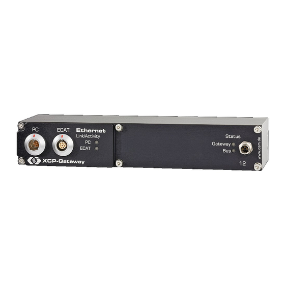
Page 13: Functional Description Led Indicators
Indicator LEDs “PC” and “ECAT” The indicator LEDs PC and ECAT are lit or are flashing if an EtherCAT module or a computer (PC) has been connected to the XCP-Gateway or when data is being transferred. Possible status categories are: LED status... - Page 14 If the Gateway LED displays the SOS code (LED is flashing red: 3x long, 3x short, 3x long), the LED flashes device start has failed and the XCP-Gateway is SOS code most likely defect. Tab. 3-2: Status-LEDs “Gateway” and “Bus”...
-
Page 15: Mounting And Installation
See datasheet “XCP-Gateway” for further technical information. The XCP-Gateway is equipped with a GORE membrane, which is essential for pressure and humidity control. To ensure reliability and performance of the device, it is essential that the small ventilation inlet in the rear side of the housing is not blocked or restricted in any way. -
Page 16: Mounting Xcp-Gateway
See datasheet “CSM MiniModule Accessories” for further technical information. If a standard mounting angle from the product range of CSM MiniModule accessories is used, the screw length may not exceed 8 mm (M4 x 8 mm). In case of combination with any other mounting material, a different screw length may be required. -
Page 17: Installing Xcp-Gateway
The two sockets embedded on the left side of the device housing’s front panel are used for connecting the XCP-Gateway to the data acquisition system PC on the one hand and to the EtherCAT measurement modules ECAT on the other hand. Via the so-called interface cable connecting the XCP-Gateway with the data acquisition system, the device is also connected to the power supply by using the cable’s... -
Page 18: Pc Socket
ECAT socket By default, a LEMO 1B connector is used for the ECAT socket. To have the device equipped with a different socket, please contact CSM. For connecting a cable to this socket, a plug of the type FGA.1B.308.CLA-xxxxx is needed. -
Page 19: Sync / Service Connector
cables for connecting EtherCAT modules (ECAT K400-xxxx) cable for connecting the XCP-Gateway with both the PC and the power supply (ECAT K420-xxxx) Parts/material required suitable connection cables (depending on the assembly) Connecting the cable ... - Page 20 For additional technical information on the topic “Daisy-chaining of measure- ment modules under load”, please contact the CSM sales department. Specific information on the cables available can be found in the datasheet.
-
Page 21: Applying Xcp-Gateway
XCP-Gateway STG-Scan MiniModul XCP-Gateway Connection cable K400-xxxx Fig. 5-1: Measurement arrangement: XCP-Gateway, EtherCAT STGMM 6 measurement modules and data acquisition system Here, the installation consists of the following items: 5 ECAT STGMM 6 measurement modules 1 XCP-Gateway 1 power supply ... -
Page 22: Configuring Xcp-Gateway
XCP-Gateway can be configured for data transfer using customer-specific parameters. For this purpose, the Windows application xx-Scan Config is being used. This utility program is supplied on the CD that is included in the shipping content of XCP-Gateway. The protocol CANopen over EtherCAT (CoE) is used for configuring the EtherCAT measurement modules connected to the XCP-Gateway. -
Page 23: Using Configuration Tool Xx-Scan Config
When creating a new configuration file ( File | New), the Select document type dialog will be displayed by default, prompting the user to select the file type required for the configuration. For XCP- Gateway and ECAT measurement modules, the file type XCP-Gateway (A2L) needs to be selected. Fig. 5-3: Select document type dialog Version 01.00... -
Page 24: Offline Configuration
The Select document type dialog opens. Fig. 5-5: Select document type dialog Select the option XCP-Gateway (A2L) for A2L file configurations and confirm by clicking on OK. The Tree view window opens (here: Config1.a2l – Tree view). - Page 25 XCP-Gateway Applying XCP-Gateway The context menu opens. Fig. 5-7: Config1.a2l – Tree view window, context menu Select Insert ( Insert). The Select device type opens. Fig. 5-8: Select device type dialog NOTICE! This dialog provides options to select module series (e.g. ECAT ADMM or ECAT STGMM) but not specific module versions (like e.g.
- Page 26 XCP-Gateway Applying XCP-Gateway Fig. 5-10: Device configuration dialog, Config1.a2l – Tree view window in the background Information as to how measurement channels and the device are configured and how the configuration data is transferred to the measurement module can be found in the online configuration chapter.
-
Page 27: Online Configuration
the ECAT measurement modules and XCP-Gateway are properly connected XCP-Gateway is properly connected to the data acquisition PC It is advisable always to use the latest version of xx-Scan Config. Specific technical information can be found in the download area of the CSM website. 5.2.3.2 Starting xx-Scan Config and selecting the communication interface ... -
Page 28: Setting Configuration Parameters
ECAT measurement modules via the XCP-Gateway. Modifications are only necessary if the default settings do not match the settings of the PC, which is used for data acquisition. - Page 29 Fig. 5-15: XCP-Gateway dialog, Configuration tab In the Parameters for Connection area, the following settings can be made: IP: Entry field for the fixed IP address of the XCP-Gateway. By default xx-Scan Config assigns the address 192.168.100.3 (host + 2).
-
Page 30: Creating Configuration File
Click on File | New ( Ctrl + N). The Select document type dialog opens. Fig. 5-17: Select document type dialog For configuration via XCP-Gateway, select the option XCP-Gateway (A2L) and confirm by clicking on OK. The Config1.a2l - Tree view window opens. -
Page 31: Scan Bus" And "Auto-Configuration
Click File | Scan Bus ( Ctrl + B). The bus is scanned for available measurement modules. Measurement modules detected are displayed in the Tree view window below the XCP-Gateway tree node. Fig. 5-20: Config1.a2l – Tree view window: detected measurement modules... - Page 32 XCP-Gateway Applying XCP-Gateway The bus will be scanned for measurement modules and possibly existing conflicts. The AutoConfig – Tree view window opens. Fig. 5-22: Auto-Configuration: “Scanning for devices…” Auto configuration is performed, the message Scanning for devices… is displayed.
-
Page 33: Configuring Measurement Channels
XCP-Gateway Applying XCP-Gateway Enter a name into the File name field (the default name is AutoConfig). See chapter 5.2.6 “Saving configuration” for more information. 5.2.4 Configuring measurement channels Example Basic configuration of ECAT measurement modules Click on the symbol left from the device entry to open the tree containing the measurement “+”... -
Page 34: Configuring The Device
XCP-Gateway Applying XCP-Gateway 5.2.5 Configuring the device Fig. 5-27: AutoConfig.a2l – Tree view window, device entry Move the mouse pointer over the device entry and double-click with the left mouse button. Move the mouse pointer over the device entry and press the Enter key. -
Page 35: Saving Configuration
XCP-Gateway Applying XCP-Gateway Furthermore, a test can be carried out to check the plausibility of the measurements. Click on the Measure button (see corresponding blue-framed button in Fig. 5-28). The following window opens. Fig. 5-30: Measurement Values window ... - Page 36 XCP-Gateway Applying XCP-Gateway Saving A2L file Click on File | Save ( Ctrl + S). The Save As dialog opens. Fig. 5-33: Save As dialog NOTICE! The Save As dialog is only used when the configuration file is saved for the first time using the Save menu function.
-
Page 37: Maintenance Services And Cleaning Instructions
(1). Fig. 6-1: XCP-Gateway, top side of housing with certification sticker (1) CSM provides a repair service for the XCP-Gateway. Please contact the CSM sales department for further details. -
Page 38: Appendix
Fig. 5-32: Program Settings dialog, Default data directory option............ 29 Fig. 5-33: Save As dialog ........................30 Fig. 5-34: Tree view window: new file name displayed in the header ..........30 Fig. 6-1: XCP-Gateway, top side of housing with certification sticker (1) ..........31 User Guide Version 01.00... -
Page 39: List Of Tables
XCP-Gateway Appendix List of tables Tab. 1-1: Text symbols ..........................1 Tab. 1-2: List of abbreviations ......................... 2 Tab. 3-1: Indicator LEDs “PC” and “ECAT” ..................... 7 Tab. 3-2: Status-LEDs “Gateway” and “Bus”................... 8 Tab. 4-1: Front view of PC socket: pin assignment ................12 Tab. - Page 40 All trademarks mentioned are property of their respective owners. This document is subject to change without notice. XCP-Gateway_UG_0100_ENG Copyright © 2014 CSM GmbH 2014-11-05...
Need help?
Do you have a question about the XCP-Gateway and is the answer not in the manual?
Questions and answers