Table of Contents
Advertisement
Quick Links
Advertisement
Table of Contents

Summary of Contents for EZiCAT EZiSYSTEM
- Page 1 EZiSYSTEM including xf-Series User Manual Version 1.1 English...
- Page 2 EZiSYSTEM, Introduction Introduction Purchase Congratulations on your purchase of an EZiSYSTEM instrument. This manual contains important safety directions as well as instructions for setting up the product and operating it. Refer to "9 Safety Directions" for further information. Read carefully through the User Manual before you switch on the product.
- Page 3 Validity of this manual This manual applies to all EZiSYSTEM instruments, which are the i-Series locators, the t- Series transmitters and accessories. Differences between the various instruments and models are marked and described.
-
Page 4: Table Of Contents
EZiSYSTEM, Table of Contents Table of Contents In this manual Chapter Page General Information How to Use this Manual i-Series General Information i-Series Instruments and Accessories How to Use the Locator General Information Locator Overview Locator Setup and Information Hazard Zone... - Page 5 How to Locate a Service Using the Sonde Care and Transport Transport Storage Cleaning and Drying Safety Directions General Introduction Intended Use Limits of Use Responsibilities Hazards of Use Electromagnetic Compatibility EMC FCC Statement, Applicable in U.S. EZiSYSTEM, Table of Contents...
- Page 6 EZiSYSTEM, Table of Contents Technical Data 10.1 Locator i-Series Technical Data 10.2 Transmitter Technical Data (1 Watt models) 10.3 Conductive Rod Technical Data 10.4 Sonde Technical Data 10.5 Maxi Sonde Technical Data 10.6 Property Connection Set Technical Data 10.7 Signal Clamp Technical Data 10.8...
-
Page 7: General Information
It is recommended to set up the product while reading through this manual. Naming convention EZiCAT i500, i550, i600, i650, i700, i750 and xf models are hereinafter referred to as Locator. Differences between the models are marked and described. EZiTEX t100, t300 and xf models is hereinafter referred to as Transmitter. -
Page 8: I-Series General Information
EZiSYSTEM, General Information i-Series General Information Description Locators are used to detect buried conductive services emitting an electromagnetic signal which is generated by a current passing through the service. Transmitters are used to apply a distinct signal to conductive services, which may not radiate electromagnetic signals or may need to be traced for a specific purpose. - Page 9 Designed to increase the detection of services with no (or little) signals on them. Generally work in conjunction with the Locator and Transmitter. Functional Check Designed to demonstrate the equipment is working satisfactorily in between service inter- vals. Refer to "Appendix A Functional Checks" for more information. EZiSYSTEM, General Information...
-
Page 10: I-Series Instruments And Accessories
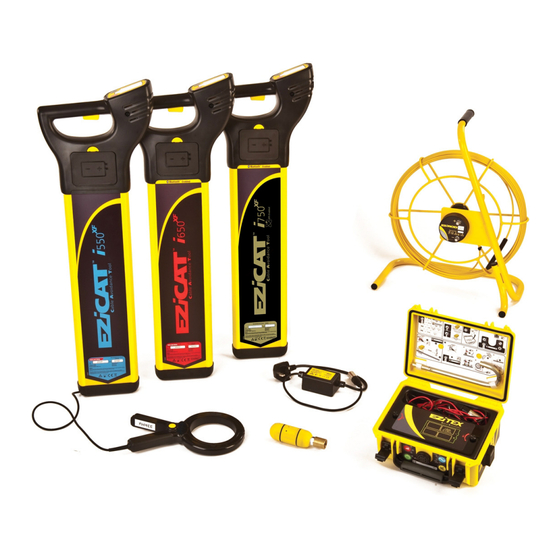
EZiSYSTEM, General Information i-Series Instruments and Accessories General information The i-Series is a collection of products used to locate buried metallic and nonmetallic services. i-Series instruments overview a) Locator b) Transmitter i-Series accessories overview a) Conductive Rod (non metallic service tracer) -
Page 11: How To Use The Locator
The highest current reading (mA) will be displayed over the service which has the transmitter connected to it. Wireless communication Data can be wirelessly transferred from the Bluetooth enabled Locator to devices which are (Bluetooth) designed to accept the information. EZiSYSTEM, How to Use the Locator... - Page 12 EZiSYSTEM, How to Use the Locator Hazard zone Provides an additional alarm, indicating the close proximity of a service emitting a Power, 8 kHz, 33 kHz (512 Hz and 640 Hz on xf models) signal. Peak hold Assists in pinpointing a service by displaying the peak reading for a short period of time.
-
Page 13: Locator Overview
6 x LR6 (AA) alkaline batteries are used. Replace all batteries when indicated. f) Case Foot The case foot can be replaced if it is worn. Contact your agency or Cable Detection author- ised service workshop. EZiSYSTEM, How to Use the Locator... - Page 14 EZiSYSTEM, How to Use the Locator Display panel overview a) Signal Strength Indicator Indicates the response of the Locator to a signal (service). b) Mode Indicators Displays the selected mode: Power, Radio, 8 kHz, (512 Hz and 640 Hz on xf models).
- Page 15 Indicates a depth reading to a service or a Sonde (Depth locators only). Service depth icon used to indicate Hazard Zone status. n) i Button Used to access the user settings and to provide a depth readout for Depth locators. EZiSYSTEM, How to Use the Locator...
-
Page 16: Locator Setup And Information
EZiSYSTEM, How to Use the Locator Locator Setup and Information Locator settings The i-Series Locators offer a range of settings which the operator can adjust to their own preference. It also displays additional service and contact information as detailed. Setting... - Page 17 3. Depress the i Button until the user settings are displayed in the display readout. 4. Press Function Button to toggle through to desired setting. 5. Press i Button to select the setting. 6. Press Function Button to activate/adjust. 7. Press i Button to store and exit. EZiSYSTEM, How to Use the Locator...
- Page 18 EZiSYSTEM, How to Use the Locator Danger The Locator may fail to detect electrical services in Power mode if an incorrect power setting is used. Precautions: Before use, verify the Locator is setup to be compatible with mains frequency supply in your country.
-
Page 19: Hazard Zone
Auto mode (Power mode only) • 512 Hz & 640 Hz (xf models only) Hazard zone Status indicator Description status indicators Hazard zone is switched on. Hazard zone on and is alarming. Hazard zone is switched off. EZiSYSTEM, How to Use the Locator... - Page 20 EZiSYSTEM, How to Use the Locator Caution The absence of a positive indication does not guarantee the non-existence of a service. Services without a detectable signal may be present. The Locators can only locate non-metallic services such as plastic pipes, typically used by the water and gas utilities, with the use of appropriate accessories.
-
Page 21: How To Locate A Service
GPS position is obtained or a 12 minute search period has elapsed. GPS search mode does not affect the locators performance and the locator can be used as normal throughout this search mode. EZiSYSTEM, How to Use the Locator... - Page 22 EZiSYSTEM, How to Use the Locator Locating process The locating process is split into three steps: • Sweep Search • Pinpointing the service • Direction of the service Sweep Search Auto mode combines the benefit of simultaneous detection in Power and...
- Page 23 Mark services with marker paint, pegs, flags or similar. Never drive pegs into the ground over the service. • The signal strength indicator does not indicate the size, depth or type of a service. EZiSYSTEM, How to Use the Locator...
- Page 24 EZiSYSTEM, How to Use the Locator Peak hold When activated peak hold will show the highest peak reading obtained during the pinpoint process. The displayed reading can be adjusted between 0 to 5 seconds. Detecting direction of the 1. Position the Locator directly service over the service.
- Page 25 • An additional depth reading should be taken with the locator lifted off the ground by approximately 100 mm (4 inches). The reading obtained should confirm the addition of this height. EZiSYSTEM, How to Use the Locator...
- Page 26 EZiSYSTEM, How to Use the Locator Depth shown and actual depth: d1 Depth shown on the EZiCAT = depth to the centre of the line. d2 Actual depth of the service. Note the difference between d1 and d2!
- Page 27 3. Press and hold down the i Button for 2 seconds until the dashed lines have scrolled through once. 4. The display readout will indi- cate the depth of the Sonde and the Sonde mode icon will be displayed. EZiSYSTEM, How to Use the Locator...
- Page 28 EZiSYSTEM, How to Use the Locator • Activating line depth will provide an inaccurate readout. • Mark utilities with marker paint, pegs, flags or similar. Never drive pegs into the ground over the service. • Additional services may be within the excavation zone, as well as the service you are taking a depth reading from.
- Page 29 The service is too shallow to register prop- metres ft-inch erly. metres ft-inch 0.3 m The service is too deep. metres ft-inch metres ft-inch 3.0 m 10ft The signal received by the Locator is too small to register properly. EZiSYSTEM, How to Use the Locator...
- Page 30 EZiSYSTEM, How to Use the Locator Information code Description Information on instru- ment label The signal received by the Locator is too large to register properly. Depth function not available. The Locator is set to the wrong mode for a depth reading...
- Page 31 Additional information on the condition and layout of the service can be ascertained such as a fault in the service, damage to the insulation, or a connection off the service, these are typically indicated by sudden reduction in the current reading. EZiSYSTEM, How to Use the Locator...
- Page 32 EZiSYSTEM, How to Use the Locator The signal (current) applied by the transmitter decreases at a uniform rate as it travels along the service. This can help to identify the service layout, as connections off it have a corresponding reduction in current. A sudden reduction in current may indicate damage to the service.
- Page 33 3. Press and release the i Button. 4. The display readout will indi- cate the depth of the service and the Line mode icon will be displayed. 5. The display readout will then indicate the Current Reading. EZiSYSTEM, How to Use the Locator...
-
Page 34: Wireless Data Communication, Where Applicable
EZiSYSTEM, How to Use the Locator Wireless Data Communication, where applicable Bluetooth Bluetooth status is indicated on the locators display, the Bluetooth symbol will be illumi- nated when Bluetooth connectivity is available. Data can be wirelessly transferred from a Bluetooth enabled Locator to a suitable data logging device, enabling the operator to capture information about the Locator’s status and the service depth. - Page 35 ASCII text description ASCII output pattern: • BT1 (standard on all Bluetooth enabled locators): DVxxxSNxxxxxxSVxxxxTMxxxxxDTdd/mm/yyCMxxSTxBTxMDxSSxxUMxDPxxxx • BT2 (model dependent): DPxxxxUMxMDxSSxxDVxxxSNxxxxxxCMxxBTxSTxSVxxxxDTxxxxxxxxTMxxxxx EZiSYSTEM, How to Use the Locator...
- Page 36 EZiSYSTEM, How to Use the Locator Data output Range Example value Description 000 to 999 Model identifier 000000 to 999999 123456 Serial number 0.00 to 9.99 3.01 Software version 00:00 to 23:59 08:30 Time: hh:mm (default = 00:00; no RTC fitted)
-
Page 37: Memory & Communication
A communication pack is available from an authorised supplier, enabling users to retrieve the locators stored log files. We recommend you to install and use the Bluetooth Adapter & Logicat Software provided in the communication pack. EZiSYSTEM, How to Use the Locator... -
Page 38: Internal Gps
EZiSYSTEM, How to Use the Locator Internal GPS Data Records The i700, i750, i750xf locators have an internal GPS module which is used to record the geographical position of use. The geographical position (Latitude and Longitude) is stored in the log file and provides information on where the locator was used. - Page 39 BT1 and BT2 connections will be maintained for a three hour period when selected, during this period the GPS will be off. The GPS will automatically activate after the three hour period has elapsed or GPS is selected from the COM Setting. EZiSYSTEM, How to Use the Locator...
-
Page 40: How To Use The Transmitter
EZiSYSTEM, How to Use the Transmitter How to Use the Transmitter General information Tracing signal The Transmitter applies an electrical current (signal) onto a buried metallic service, which enables the service to be traced and identified by the Locator operating in the same mode. - Page 41 This is the most efficient way of applying a signal to a service, and should be used when- ever possible. The Transmitter’s cable set or any of the available accessories are connected to the service which is to be traced or identified. EZiSYSTEM, How to Use the Transmitter...
-
Page 42: Transmitter Overview
EZiSYSTEM, How to Use the Transmitter Transmitter Overview Transmitter main parts a) Battery Cover b) Accessory Compartment c) Connection Socket Used to connect accessories directly to metallic services. (Standard: crocodile clip cable set.) d) Speaker e) Power Output Control and Indicator Press the control to set the Transmitters power output. - Page 43 The battery indicator flashes to indicate a poor battery condition. 1. Unscrew the fastener and open the cover. 2. Replace all batteries with four new LR20 (D) type alkaline batteries, or remove and recharge the battery pack if rechargeable batteries are fitted. EZiSYSTEM, How to Use the Transmitter...
- Page 44 EZiSYSTEM, How to Use the Transmitter Warning Risk of electric shock when removing the Transmitter's battery pack. Precautions: Before removing the battery pack switch the transmitter off and remove any cable set or accessories from the connection socket. Caution The Transmitter's battery pack may get hot after prolonged use.
-
Page 45: How To Locate A Service Using The Transmitter
LEDs are all lit throughout the test sequence. Default mode selection 33 kHz and power output level two is automatically selected. Induction mode is selected unless the Trans- mitter's cable set or accessories are connected. EZiSYSTEM, How to Use the Transmitter... - Page 46 EZiSYSTEM, How to Use the Transmitter Using the Transmitter in Induction mode 1. Switch the Transmitter on, observe the Induction mode LED is illuminated and the battery level is adequate. Change batteries when indicated. Select the required power output level and frequency output.
- Page 47 LED & audible tone changes from pulsed to continuous. 6. Trace the signal using the Locator set to the same operating mode. Refer to "2 How to Use the Locator" for more information. EZiSYSTEM, How to Use the Transmitter...
- Page 48 EZiSYSTEM, How to Use the Transmitter Danger Connecting the cable set to a live service can result in an electric shock. Precautions: The connection cable set should never be connected directly to a live service. Warning The transmitter is capable of outputting potentially lethal voltages.
-
Page 49: How To Use The Conductive Rod
Flexible, Glass Fibre sheathed, which incorporates copper wires to conduct the signal. c) Connection Terminals Used to connect to the Transmitter. d) Frame Houses the flexible rod. Can be used in both vertical (shown) and horizontal orientation. EZiSYSTEM, How to Use the Conductive Rod... -
Page 50: How To Locate A Service Using The Conductive Rod
EZiSYSTEM, How to Use the Conductive Rod How to Locate a Service Using the Conductive Rod Using the Conductive 1. Insert the rod into the pipe, duct, Rod in Line mode conduit or drain until the desired length is in place. - Page 51 The signal applies itself along the length of the Conductive Rod. 4. Trace the length of the rod using the Locator set to the same frequency. At least half the Conductive Rod needs to be uncoiled when in use. EZiSYSTEM, How to Use the Conductive Rod...
-
Page 52: How To Use The Signal Clamp
EZiSYSTEM, How to Use the Signal Clamp How to Use the Signal Clamp General Information Description The Signal Clamp provides a safe technique of applying a signal to services such as telecom cables, etc. It is connected to the Transmitter and then clipped around the service. -
Page 53: How To Locate A Service Using The Signal Clamp
A hazardous signal may be present on the connection plug of the Signal Clamp when clipped over a live service. Precautions: The clamp should be connected to the Transmitter before clamping around a live service. EZiSYSTEM, How to Use the Signal Clamp... - Page 54 EZiSYSTEM, How to Use the Signal Clamp Danger A hazardous signal may be present on the service causing personal harm. Precautions: Do not use on electrical services which have impaired, or no insulation. If in doubt do not use.
-
Page 55: How To Use The Property Connection Set
Supply is not interrupted by the applied signal and the risk of serious injury is greatly reduced. Property Connection Set Overview Property Connection Set main parts a) Mains plug connector b) In line isolator c) Transmitter plug connector EZiSYSTEM, How to Use the Property Connection Set... -
Page 56: How To Locate A Service Using The Property Connection Set
EZiSYSTEM, How to Use the Property Connection Set How to Locate a Service Using the Property Connection Set Using the Property Connection Set 1. Connect the Property Connection Set to the Transmitter. 2. Connect the Property Connection Set to a live mains outlet. Ensure the switch on the mains is on. - Page 57 Precautions: Do not use on electrical services which have impaired, or no insulation. If in doubt do not use. Replace damaged Property Connection Set cable assembly before use. EZiSYSTEM, How to Use the Property Connection Set...
-
Page 58: How To Use The Sonde
EZiSYSTEM, How to Use the Sonde How to Use the Sonde General Information Description The Sonde is a signal transmitter used to trace drains, sewers and other non conductive services. It can be attached to a range of equipment including drain rods, boring tools and inspection cameras. - Page 59 2. Hold Sonde upright. Confirm green LED is continuous. 3. Wait approximately 10 seconds for the green LED to start flashing. 4. With the green LED flashing, the Sonde is ready for use at 33 kHz. EZiSYSTEM, How to Use the Sonde...
- Page 60 EZiSYSTEM, How to Use the Sonde Changing to 8 kHz mode: 1. Unscrew and remove end cap. Insert battery, positive end first. Refit end cap securely. 2. Hold Sonde upright. Confirm green light is continuous. 3. Rotate Sonde so the LED points down and wait approxi- mately 1 second.
-
Page 61: Maxi Sonde Overview
3x LR6 (AA) battery d) End cap and M10 connection point The thread on the Maxi Sonde is a male M10, and comes with adaptors to both British and European drain rods. EZiSYSTEM, How to Use the Sonde... - Page 62 EZiSYSTEM, How to Use the Sonde Changing the frequency Changing to 33 kHz mode: output 1. Unscrew and remove end cap. 2. Insert the batteries, positive end first. 3. Refit end cap securely. With the green LED flashing, the Sonde is ready for use at 33 kHz.
- Page 63 3. Refit end cap securely. With the amber LED flashing, the Sonde is ready for use at 8 kHz. LEDs indicating battery If the amber and green LEDs are condition flashing you need to replace the batteries. EZiSYSTEM, How to Use the Sonde...
-
Page 64: How To Locate A Service Using The Sonde
EZiSYSTEM, How to Use the Sonde How to Locate a Service Using the Sonde Attaching the Sonde to a Once the function of the Sonde has been checked with a Locator set to the same operating drain rod mode it can be attached to drain rods or other means of guiding it into the service being traced. - Page 65 The Locator will pick up a pool of signal with a null point at the centre. This is an accurate method, but it is essential to ensure the Sonde is vertical. EZiSYSTEM, How to Use the Sonde...
-
Page 66: Care And Transport
EZiSYSTEM, Care and Transport Care and Transport Transport Transport in the field When transporting the equipment in the field, always make sure that you carry the product in its original transport container. Transport in a road Never carry the product loose in a road vehicle, as it can be affected by shock and vibration. -
Page 67: Cleaning And Drying
40°C / 104°F and clean them. Do not repack until everything is completely dry. Cables and plugs Keep plugs clean and dry. Blow away any dirt lodged in the plugs of the connecting cables. EZiSYSTEM, Care and Transport... -
Page 68: Safety Directions
EZiSYSTEM, Safety Directions Safety Directions General Introduction Description The following directions should enable the person responsible for the product, and the person who actually uses the equipment, to anticipate and avoid operational hazards. The person responsible for the product must ensure that all users understand these direc- tions and adhere to them. -
Page 69: Limits Of Use
The manufacturers of non Cable Detection accessories for the product are responsible for Cable Detection developing, implementing and communicating safety concepts for their products, and are accessories also responsible for the effectiveness of those safety concepts in combination with the Cable Detection product. EZiSYSTEM, Safety Directions... -
Page 70: Hazards Of Use
EZiSYSTEM, Safety Directions Person in charge of the The person in charge of the product has the following duties: product • To understand the safety instructions on the product and the instructions in the user manual. • To ensure that it is used in accordance with the instructions. - Page 71 Transmitter. This signal is radiated from the centre of the service. This is even more important when the signal is produced by a Sonde, lying in a large diam- eter conduit! Precautions: Always compensate depth reading for service size. EZiSYSTEM, Safety Directions...
- Page 72 EZiSYSTEM, Safety Directions Danger The Locator may fail to detect electrical services in Power mode if an incorrect power setting is used. Precautions: Before use, verify the Locator is setup to be compatible with mains frequency supply in your country. Options are 50 or 60 Hz. Refer to "Appendix B World Frequency Zones" (User Manual) for more information.
- Page 73 Notify others who may be working on or around the service. Warning The transmitter is capable of outputting potentially lethal voltages. Precautions: Care should be taken when using the maximum power output level. EZiSYSTEM, Safety Directions...
- Page 74 EZiSYSTEM, Safety Directions Warning Risk of electric shock when removing the Transmitter's battery pack. Precautions: Before removing the battery pack switch the transmitter off and remove any cable set or accessories from the connection socket. Caution The Transmitter's battery pack may get hot after prolonged use.
-
Page 75: Electromagnetic Compatibility Emc
Description The term Electromagnetic Compatibility is taken to mean the capability of the product to function smoothly in an environment where electromagnetic radiation and electrostatic discharges are present, and without causing electromagnetic disturbances to other equip- ment. EZiSYSTEM, Safety Directions... - Page 76 EZiSYSTEM, Safety Directions Warning Electromagnetic radiation can cause disturbances in other equipment. Although the product meets the strict regulations and standards which are in force in this respect, Cable Detection cannot completely exclude the possibility that other equipment may be disturbed.
- Page 77 Do not operate the product with radio or digital cellular phone devices in aircraft. • Do not operate the product with radio or digital cellular phone devices for long periods with it immediately next to your body. EZiSYSTEM, Safety Directions...
-
Page 78: Fcc Statement, Applicable In U
EZiSYSTEM, Safety Directions FCC Statement, Applicable in U.S. Warning This equipment has been tested and found to comply with the limits for a Class B digital device, pursuant to part 15 of the FCC rules. These limits are designed to provide reasonable protection against harmful interference in a residential installation. - Page 79 Labelling Locator EZiSYSTEM, Safety Directions...
- Page 80 EZiSYSTEM, Safety Directions Labelling Transmitter...
- Page 81 Flexible, Glass Fibre sheathed, which incorporates copper wires to conduct the signal. c) Connection Terminals Used to connect to the Transmitter. d) Frame Houses the flexible rod. Can be used in both vertical (shown) and horizontal orientation. EZiSYSTEM, Safety Directions...
- Page 82 EZiSYSTEM, Safety Directions Signal Clamp a) Transmitter plug connector b) Jaws c) Handle d) Cable Property Connection Set e) Mains plug connector f) In line isolator g) Transmitter plug connector...
-
Page 83: Technical Data
2 m / 7 ft Transmitter mode Dependent on Transmitter and service type Typical depth accuracy EZiCAT i550, i650, i750 EZiCAT i550xf, i650xf, i750xf 10% of depth in line or Sonde 10% of depth in line or Sonde 0.3 to 3.0 m (1 to 10 ft) Line Mode 0.3 to 3.0 m (1 to 10 ft) Line Mode... - Page 84 EZiSYSTEM, Technical Data Operating frequencies Mode Frequency Power mode 50 Hz or 60 Hz Radio mode 15 kHz to 60 kHz 8 kHz mode 8.192 (8) kHz 33 kHz mode 32.768 (33) kHz Auto mode Power mode and Radio mode...
- Page 85 Continuous tone (different pitch for each mode). 8 kHz and 33 kHz mode: Pulsed tone (different pitch for each mode). 512 Hz and 640 Hz mode: Pulsed tone (different pitch for each mode). All tones are different. • Pneumatic headphone sockets are integrated EZiSYSTEM, Technical Data...
- Page 86 EZiSYSTEM, Technical Data Internal battery Type: 6 x LR6 (AA) alkaline Typical operating time: 40 hrs intermittent use at 20°C / 68°F; in 8 kHz mode or 33 kHz mode Instrument dimensions 85 mm/3.4 Inches 760 mm/30 Inches 250 mm/10 Inches...
- Page 87 • FCC Part 15 (applicable in US) regulations • Hereby, Cable Detection Ltd, declares that the EZiCAT i500/i550/i600/i650/i700/i750/i500xf/i550xf/i600xf/i650xf/i700xf/i750xf is in compliance with the essential requirements and other relevant provisions of Directive 1999/5/EC. The declaration of conformity may be consulted at http://www.cabledetection.co.uk/ce.
- Page 88 EZiSYSTEM, Technical Data 10.2 Transmitter Technical Data Typical detection range Mode Output Induction mode Up to 1 W max. Connection mode t100 & t100xf Up to 1 W max. when connected to a buried service with an impedance of 300 Ω.
- Page 89 & t100xf: Typical operating time 15 hrs intermittent use at 20 °C / 68 °F t300 & t300xf: Instrument dimensions 113 mm/4.45 inches 206 mm/8.11 inches 250 mm/9.84 inches Weight Instrument: 2.5 kg / 5.5 lbs (including batteries) EZiSYSTEM, Technical Data...
- Page 90 EZiSYSTEM, Technical Data Environmental Type Description specifications Temperature Operating -20°C to +50°C -4°F to +122°F Storage -40°C to +70°C -40°F to +158°F Protection against With cover open IP65 (IEC 60529) Water, Dust and Dust-tight, Low power Sand water jets. With cover closed...
-
Page 91: Conductive Rod Technical Data
30 m/99 ft; 50 m/165 ft; 80 m/263 ft (maximum). Reel length dependant Operating transmission Dependent on Transmitter frequencies Instrument dimensions 490 mm/19.3 Inches 210 mm/8.3 Inches 440 mm/17.3 Inches Weight Instrument: 7.3 kg / 16.1 lbs EZiSYSTEM, Technical Data... - Page 92 EZiSYSTEM, Technical Data Environmental Type Description specifications Temperature Operating -20°C to +50°C -4°F to +122°F Storage -40°C to +70°C -40°F to +158°F Protection against Frame IP54 (IEC 60529) Water, Dust and Dust-protected Sand Fully submersible Humidity 95% RH non condensing...
-
Page 93: Sonde Technical Data
1 x LR6 (AA) alkaline Typical operating time: 40 hrs intermittent use at 20°C / 68°F; in 8 kHz mode or 33 kHz mode Instrument dimensions Ø38 mm/1.5 Inches 120 mm/4.7 Inches Weight Instrument: 0.18 kg / 0.4 lbs (including batteries) EZiSYSTEM, Technical Data... - Page 94 EZiSYSTEM, Technical Data Environmental Type Description specifications Temperature Operating -20°C to +50°C -4°F to +122°F Storage -40°C to +70°C -40°F to +158°F Protection against Water, Dust Fully submersible and Sand Humidity 95% RH non condensing The effects of condensation are to be effectively counteracted by periodically drying out the product.
-
Page 95: Maxi Sonde Technical Data
Typical operating time: 10 hrs continuous use at 20°C / 68°F; in 8 kHz mode or 33 kHz mode Instrument dimensions Ø55 mm/2.17 Inches 300 mm / 12 Inches Weight Instrument: 0.830 kg / 1.18 lbs (including batteries) EZiSYSTEM, Technical Data... - Page 96 EZiSYSTEM, Technical Data Environmental Type Description specifications Temperature Operating -20°C to +50°C -4°F to +122°F Storage -40°C to +70°C -40°F to +158°F Protection against Water, Dust IP68 (IEC 60259) and Sand Fully submersible Submersion level: 3 bar pressure/30 m water...
-
Page 97: Property Connection Set Technical Data
10.6 Property Connection Set Technical Data Operating transmission • 32.768 (33) kHz frequencies Instrument dimensions 80 mm/3.1 Inches 100 mm/3.9 Inches Weight Instrument: 0.15 kg / 0.3 lbs EZiSYSTEM, Technical Data... - Page 98 EZiSYSTEM, Technical Data Environmental Type Description specifications Temperature Operating -20°C to +50°C -4°F to +122°F Storage -40°C to +70°C -40°F to +158°F Protection against Water, Dust IP54 (IEC 60529) and Sand Dust-protected Humidity 95% RH non condensing The effects of condensation are to be effectively counteracted by periodically drying out the product.
-
Page 99: Signal Clamp Technical Data
Signal Clamp Technical Data Operating transmission 32.768 (33) kHz frequencies when used with a signal transmitter set in 33 kHz mode. Instrument dimensions 250 mm/9.8 Inches 142 mm/5.6 Inches 100 mm/4 Inches Weight Instrument: 0.354 kg / 0.76 lbs EZiSYSTEM, Technical Data... - Page 100 EZiSYSTEM, Technical Data Environmental Type Description specifications Temperature Operating -20°C to +50°C -4°F to +122°F Storage -40°C to +70°C -40°F to +158°F Protection against Water, Dust IP54 (IEC 60529) and Sand Dust-protected Humidity 95% RH non condensing The effects of condensation are to be effectively counteracted by periodically drying out the product.
-
Page 101: Multi Clamp Technical Data
Operating transmission • 8 kHz frequencies • 33 kHz • Mixed: 8/33 kHz • 512 Hz • 640 Hz Instrument dimensions 250 mm/9.84 Inches 129 mm/5.07 Inches 80 mm/3.15 Inches Weight Instrument: 0.82 kg / 1.8 lbs EZiSYSTEM, Technical Data... - Page 102 EZiSYSTEM, Technical Data Environmental Type Description specifications Temperature Operating -20°C to +50°C -4°F to +122°F Storage -40°C to +70°C -40°F to +158°F Protection against Water, Dust IP54 (IEC 60529) and Sand Dust-protected Humidity 95% RH non condensing The effects of condensation are to be effectively counteracted by periodically drying out the product.
-
Page 103: International Limited Warranty
EZiSYSTEM, International Limited Warranty... - Page 104 EZiSYSTEM, Functional Checks Appendix A Functional Checks Locator Functional Check Checking the function Before any tests can be carried out it is vital to check the status of the unit, its batteries and basic functionality. The following list is used to achieve this.
- Page 105 3. Press and release the i Button to activate the depth measurement. 4. Record the depth. 5. If the depth reading deviates from the normal value or an error code is displayed, the Locator should be returned for service. EZiSYSTEM, Functional Checks...
- Page 106 EZiSYSTEM, Functional Checks If any of these tests give no response or a significantly different response from normal, the Locator should be returned for service. Functional test check list Functional Test Check List Unit: Serial Number: Comments: Locator... Test...
- Page 107 Return for repair Response width and peak value similar to test unit. 12. Depth Mode Return for repair Gives same result as test unit (Depth Locator (10% accuracy). only) • 8 kHz, 33 kHz • 512 Hz, 640Hz (xf models) Tested by: Date: EZiSYSTEM, Functional Checks...
- Page 108 EZiSYSTEM, Functional Checks Transmitter Functional Check Checking the function The purpose of the following procedure is to verify the performance of the signal Trans- mitter. Before any tests can be carried out it is vital to check the status of the unit, its batteries and basic functionality.
- Page 109 3. Battery check The battery indicator flashes to indicate a poor battery condition. Replace all batteries with four new LR20 (D) type alkaline batteries, or remove and recharge the battery pack if rechargeable batteries are fitted. EZiSYSTEM, Functional Checks...
- Page 110 EZiSYSTEM, Functional Checks Checking the The purpose of the following procedure is to verify the performance of the Transmitter. It is performance important that the test is conducted away from areas of electromagnetic interference. 1. Plug the Transmitter’s cable set into the connection socket.
- Page 111 The transmitter is capable of outputting potentially lethal voltages. Precautions: Care should be taken when handling exposed or non-insulated connections including; the connection cables sets, the Earth Pin and the connection to the service. Notify others who may be working on or around the service. EZiSYSTEM, Functional Checks...
- Page 112 EZiSYSTEM, Functional Checks Functional test check list Functional Test Check List Unit: Serial Number: Comments: Transmitter... Test Operative Fail analysis Notes 1. Casing Return for repair/ Casing should be free of Replace damage. 2. Labels Return for repair/ Body labels must be legible Replace and intact.
- Page 113 Reduced or no output signal. Replace 8. Connection Return for repair/ Faulty cable. mode; no change Replace in audio indica- tion 9. Connection Return for repair/ No output signal. mode; no change Replace in audio indica- tion Tested by: Date: EZiSYSTEM, Functional Checks...
- Page 114 EZiSYSTEM, Functional Checks Conductive Rod Functional Check Checking the function The purpose of the following procedure is to verify the performance of the Conductive Rod. To carry out this test the following are required: • A Transmitter for generating the signal in the Sonde and Line mode tests •...
- Page 115 One or both internal wires Locator does not Replace are open or short circuit. detect signal 3. Line mode: Return for repair/ One or both internal wires Locator does not Replace are open or short circuit. detect signal Tested by: Date: EZiSYSTEM, Functional Checks...
- Page 116 EZiSYSTEM, Functional Checks Sonde Functional Check Checking the function The purpose of the following procedure is to enable a user to verify the performance of the Sonde. To carry out this test the following are required: • A Locator to detect the signal.
- Page 117 4. Repeat this with Sonde and Locator in 8 kHz. 2 m/6.56 ft 5 m/16.4 ft 5 m/16.4 ft If any of these tests give no response or a significantly different response from normal, the Sonde should be returned for service. EZiSYSTEM, Functional Checks...
- Page 118 EZiSYSTEM, Functional Checks Functional test check list Functional Test Check List Unit: Serial Number: Comments: Sonde... Test Operative Fail analysis Notes 1. Casing Fail Casing should be free of damage. 2. Screw thread and Fail Screw thread must be intact seal and seal in place.
- Page 119 120 V / 60 Hz Tonga 230 V / 50 Hz Panama 120 V / 60 Hz Puerto Rico 120 V / 60 Hz Trinidad & Tobago 115-230 V / 60 Hz Virgin Islands 120 V / 60 Hz EZiSYSTEM, World Frequency Zones...
- Page 120 EZiSYSTEM, World Frequency Zones Europe Albania 230 V / 50 Hz Slovenia 230 V / 50 Hz Austria 230 V / 50 Hz Spain 230 V / 50 Hz Belgium 230 V / 50 Hz Sweden 230 V / 50 Hz...
- Page 121 Mali 220 V / 50 Hz Mauritania 220 V / 50 Hz Mauritius 230 V / 50 Hz Morocco 127-220 V / 50 Hz Mozambique 220 V / 50 Hz Namibia 220 V / 50 Hz EZiSYSTEM, World Frequency Zones...
- Page 122 EZiSYSTEM, World Frequency Zones Asia Abu Dhabi 230 V / 50 Hz Oman 240 V / 50 Hz Afghanistan 220 V / 50 Hz Pakistan 230 V / 50 Hz Armenia 220 V / 50 Hz Philippines 110-220 V / 60 Hz...
-
Page 123: Index
Distance along conductor .......... 83 Functional Check ............116 Technical Data ..............83 Temperature Conductive Rod Operating ............... 92 Storage ..............92 Locator Operating ............... 87 Storage ..............87 Property Connection Set Operating ............... 98 Storage ..............98 Signal Clamp EZiSYSTEM, Index... - Page 124 Total Quality Management: Our commitment to total customer satisfaction. Cable Detection Ltd, Staffordshire, UK, has been certified as being equipped with a quality system which meets the International Standards of Quality Management and Quality Systems (ISO standard 9001). Ask your local Cable Detection dealer for more information about our TQM program.
Need help?
Do you have a question about the EZiSYSTEM and is the answer not in the manual?
Questions and answers