Table of Contents
Advertisement
Quick Links
INSTALLATION GUIDE
MARKETING COMMUNICATIONS
11/13/12
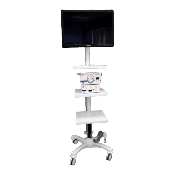
3DHD VISION SYSTEM
@2012 by ConMed Corporation- All rights reserved.
MCM2012221
This publication is protected by copyright. Copying, disclosure to others, or sue of this publication is prohibited without
express written consent of ConMed Corporation. ConMed Corporation reserves the right to make changes show herein
without notice or obligation. Contact ConMed Corporation or your representative for the latest information.
Advertisement
Table of Contents

Summary of Contents for ConMed 3DHD
- Page 1 This publication is protected by copyright. Copying, disclosure to others, or sue of this publication is prohibited without express written consent of ConMed Corporation. ConMed Corporation reserves the right to make changes show herein without notice or obligation. Contact ConMed Corporation or your representative for the latest information.
- Page 2 11/9/12 3DHD VISION SYSTEM This installation guide is for use by ConMed Distributors to ensure proper set up of the ConMed 3DHD Vision System. For more detailed information and for trouble shooting by product please refer to the product User Manuals which can be found with each of the individual 3DHD Vision System components.
- Page 3 Secure the clip and power cord back onto the Video Cart using the existing Cap Screw and Washer. MOUNTING INSTRUCTIONS FOR VIDEO DISPLAY: (SONY) Open 8272-14 Sony* 3DHD video display monitor box and remove power supply Inspect for any damage including cosmetic damages.
- Page 4 INSTALLATION GUIDE MARKETING COMMUNICATIONS 11/9/12 3DHD VISION SYSTEM Figure 4 Figure 5 Figure 6 Attach the Mounting Bracket to the Sony Monitor Power Supply as shown in Figure 4. a. Remove backing from the double sided tape on the Mounting Bracket.
-
Page 5: In Figures
Attach one of the 1 m IEC 320 power cords to power supply as shown in Figure 11. Figure 11 Open 3DHD controller packaging and remove HD-SDI cables. Figure 12 indicates Left and Right Cables. Left = All Black Cable... - Page 6 INSTALLATION GUIDE MARKETING COMMUNICATIONS 11/9/12 3DHD VISION SYSTEM Run the HD-SDI video cables through cart extension channel as shown in Figures 13 and 14: Figure 13 Figure 14 Right angle end goes to the CCU (middle shelf). Reinstall plastic cart column covers.
-
Page 7: Connect Right (White) Hd-Sdi Video Cable To Sony* 3G Card Input2
INSTALLATION GUIDE MARKETING COMMUNICATIONS 11/9/12 3DHD VISION SYSTEM Attach monitor video display to cart’s Vesa mounting bracket. Attach the remaining two bottom screws to remaining holes in the Vesa* mounting bracket, tighten all screws, Vesa* bracket should like pictures shown... - Page 8 INSTALLATION GUIDE MARKETING COMMUNICATIONS 11/9/12 3DHD VISION SYSTEM Remove existing vesa mounting plate from the cart and install 200/200 Vesa Plate as shown below in Figures 21 and 22. Figure 21 Figure 22 200/200 VESA MOUNTING* PLATE INSTALLATION 1. Remove the four (4) existing screws from the front of the existing tilt / swivel VESA mount* plate, and remove the existing VESA mounting* plate.
- Page 9 Figure 26 Engage Clip 3DHD CONTROLLER: Unpack the 8170-6 3DHD controller. Inspect for any damages, including cosmetic damages. Place the controller on the middle shelf as shown below. Connect video cables to proper left (black) and right ( white banded) HD-SDI outputs on controller.
- Page 10 3DHD LIGHT SOURCE: Unpack the 8050-2 3DHD light source. Inspect for any damage, including cosmetic damages. Place the light source on top of the 3DHD controller (position feet in detents on controller cover). As shown in Figure 28. Figure 28 Attach power cord to light source.
-
Page 11: Operational Checks
Unpack 3DHD Vision Systems 3DHD glasses, 8272-15 and 8272-16 overwear glasses. Put on a pair of 3DHD Vision Systems 3D glasses and view the monitor video display screen. Color bars should be present in both right and left eyes. The on screen display (OSD) should only be present in the left eye. - Page 12 INSTALLATION GUIDE MARKETING COMMUNICATIONS 11/9/12 3DHD VISION SYSTEM The on screen display (OSD) on the monitor video display screen should display the following as shown in Figures 32. OSD Reference for text only Figure 32 Aim and focus Camera Head at an object in the room that has a horizontal edge (such as a shelf or top of door or doorway).
-
Page 13: Light Guide
INSTALLATION GUIDE MARKETING COMMUNICATIONS 11/9/12 3DHD VISION SYSTEM Attach (Dual Channel or Single Channel) Stereo Endoscope to appropriate Camera Head by pushing down coupler latching feature. Insert Endoscope and releasing coupler latching feature, as shown in Figure 34. Figure 34 WARNING: Ensure Endoscope is securely locked to Camera Head. - Page 14 3DHD VISION SYSTEM LIGHT SOURCE TESTING: Turn on 3DHD light source by pressing power button on upper left corner. When the power switch is pressed the Stand-by Light will blink and there will be a 3 to 4 second delay before Xenon Lamp illuminates, at this time the system is performing a self-diagnostic check.
- Page 15 MARKETING COMMUNICATIONS 11/9/12 3DHD VISION SYSTEM 3DHD SYSTEM TESTING: Put on a pair of Viking Systems 3D Glasses and aim 3DHD Camera Head (with Scope and Light Guide attached) at a non-reflective white object, as shown in Figure 37. Figure 37...
- Page 16 INSTALLATION GUIDE MARKETING COMMUNICATIONS 11/9/12 3DHD VISION SYSTEM Once white balance completes the on screen display (OSD) looks (for a brief period) as shown is Figure 39. WHITE BALANCE MODE LAPAROSCOPY 1 Figure 39 Press and hold the white button on the 3D camera head. The white balance should initiate and complete as displayed above.
- Page 17 INSTALLATION GUIDE MARKETING COMMUNICATIONS 11/9/12 3DHD VISION SYSTEM ALIGNMENT OF THE SCOPE/CAMERA: The alignment should be checked periodically. WARNING: If the system comes out of alignment it WILL cause eye strain and discomfort. In severe cases 3D effect will be lost.
-
Page 18: Monitor Placement
Refer to Monitor User Manual, for illustrations and proper viewing angles. 3DHD 2D CAMERA HEAD TESTING IF PURCHASED WITH SYSTEM: Remove 8170-7 2D camera head from its packaging and inspect the camera housing and cable for cuts, tears, cracks, or other defects. -
Page 19: System Shutdown
INSTALLATION GUIDE MARKETING COMMUNICATIONS 11/9/12 3DHD VISION SYSTEM Press and release the left (blue) button on the camera head and the control unit will beep once. Now press and hold the same left (blue) Button and the control unit will beep twice.
Need help?
Do you have a question about the 3DHD and is the answer not in the manual?
Questions and answers