Table of Contents
Advertisement
Advertisement
Table of Contents

Related Manuals for Brink Air Control


Summary of Contents for Brink Air Control
- Page 1 Installation regulations Brink Air Control English...
-
Page 2: Table Of Contents
9 Environment........22 1.1 Description Brink Air Control....3 10 Troubleshooting and quarantee. -
Page 3: User Manual
We kindly request you to carefully go through this information before using the product. This user’s manual is intended for the Brink Air Control installer and end user. You can retrieve the required information from the user’s manual via the table of contents. -
Page 4: Technical Specification
The Brink Air Control should be placed and used in a space with the correct ambient conditions for proper operation. The Brink Air Control may only be mounted on the indoors, but not on the vicinity of a heat source, a radiator, in a draft or in a humid environment. -
Page 5: Precautionary Measures And Safety Instructions
Take note! Never use parts other than original parts. Take note! Only use the Brink Air Control indoors, at temperatures between 0 °C and 50 °C and with a relative humidity between 10% and 90%. Take note! All settings (excluding the filter message) will be lost if the Brink Air Control breaks down or if the factory settings are reset. -
Page 6: During Use
Never apply water and/or (cleaning) liquid to the screen. 3.5 For the environment Take note! The Brink Air Control may not be removed as unsorted urban waste, but should be treated separately. Take note! Make enquiries within your own region, where the Brink Air Control can be handed in when use has been terminated. -
Page 7: Assembly And Installation
Consult ( ® During placement page 5) for more information on placing the Brink Air Control. 4.1.3 Electrical connection The following actions should be performed to connect the Brink Air Control electrically ( ® Image electrical connection page 28 ): ·... -
Page 8: Bracket
· Press returnkey "2" as many times as necessary to get to the main screen Take note! The names of the described menu items will not correspond with this user manual’s menu items if the Brink Air Control is set to a language other than Dutch. Brink Air Control 614884-A... -
Page 9: Setting Time
4.2.2 Setting time You can set the time. The time is visible on the main screen The Brink Air Control only has 24 hour representation. Perform the following actions to set the time ( ® Image overview operational control page 27 ): ·... -
Page 10: Selecting A Device Connected To The Brink Air
4.2.4 Selecting a device connected to the Brink Air Control You can choose the device you want to regulate with the control if multiple devices are connected to Brink Air Control. Proceed as follows to set the appliance selection (see ®... -
Page 11: Description Of Operation; Manner Of Use
5 Description of operation; manner of use You can increase or decrease the ventilation mode with the Brink Air Control. You can do this by setting a program. You can temporarily override the program while it is running. 5.1 Navigation: general description Navigating through menus The Brink Air Control has menus that you can navigate through. -
Page 12: Creating A P1 Programme
· Press "1" to confirm the ventilation mode for period 1 You have set the ventilation mode for period 1. You can set period 2 through 6 in the same manner. A period ends when a new one starts. Brink Air Control 614884-A... -
Page 13: Creating A P2 Programme
· Press setting knob "1" to confirm the airflow for period 1 You have set the ventilation mode for period 1 You can set period 2 through 6 in the same manner. A period ends when a new one starts. Brink Air Control 614884-A Brink / 13... -
Page 14: Creating A P3 Programme
· Change ‘Start time’ by turning setting knob "1" ; You have a range of between 3.00u and 2.59u · Press setting knob "1" to confirm ‘Start time’ Now set the ventilation mode for period 1. Perform the following actions for this: · Select 'Ventilatiestand' by turning setting knob "1" Brink Air Control 614884-A... - Page 15 If you have created a day program for Monday, you can do the same for the other days of the week. Then repeat the steps from paragraph 5.3.4, but, after (*) choose another day instead of ‘Monday’. Brink Air Control 614884-A Brink / 15...
-
Page 16: Activating Programma Type (P1, P2 Or P3)
5.4 Activating programma type (P1, P2 or P3) The Brink Air Control has three types of weekly programs P1, P2 and P3. You can program the weekly programs by yourself, for more information see paragraph .® Weekly programmes P1, P2 and P3 page 11. -
Page 17: Setting Ventilation Mode Values
You can set debit 1 through 3 in the same manner as described above for Airflow 0 (Holiday). Take note! You cannot feed in a value, lower than value of a lower Airflow position, for a higher (Airflow Holiday < Airflow Reduced < Airflow Normal < Airflow High). Brink Air Control 614884-A Brink / 17... -
Page 18: Retrieving Settings
You can look at, but not change, the settings via the info menu. 5.9 Factory setting connected device A device has been connected to the Brink Air Control. It is possible to set back all this device’s settings to the factory settings. Perform the following actions for this ( ®... -
Page 19: Maintenance
6.2 Cleaning or replacing filter 6.2.1 Filter notification The filters in the device, connected to the Brink Air Control, should be cleaned or replaced when the text ‘FILTER’ appears on the Brink Air Control display ( ® Image filter notification page 30 ). -
Page 20: Dismanteling
7 Dismanteling Warning! You are not permitted to dismantle the Brink Air Control or parts of the Brink Air Control by yourself. This may only be done by a maintenance mechanic approved by Brink Climate Systems B.V.. Brink Air Control 614884-A... -
Page 21: Repair
8 Repair Warning! You are not permitted to open or repair the Brink Air Control or parts of the Brink Air Control by yourself. This may only be done by a maintenance mechanic approved by Brink Climate Systems B.V.. Brink Air Control 614884-A... -
Page 22: Environment
Make enquiries within your own region, where the Brink Air Control can be handed in when use has been terminated. Do not throw away electrical devices or parts, but check if (parts of) the Brink Air Control cannot be handed in, recycled or re-used. -
Page 23: Troubleshooting And Quarantee
Brink Climate Systems B.V. Mailbox 11 NL-7950 AA, Staphorst, The Netherlands The right to guarantee lapses in case of incorrect or improper use of the Brink Air Control and failure to follow the user indications in this user’s manual. Warning! Making changes to the Brink Air Control hardware or software is not permitted. -
Page 24: Appendix 1: Standard Settings Weekly Programmes
11 Appendix 1: Standard settings weekly programmes 11.1 Standard programme P1 Week (Monday through Sunday) Period Start time Ventilation mode 07.00 08.00 17.00 22.00 Not set Not set Brink Air Control 614884-A... -
Page 25: Standard Programme P2
Week (Monday through Friday) Weekend (Saturday and Sunday) Period Start time Ventilation mode Period Start time Ventilation mode 07.00 08.00 08.00 23.00 17.00 Not set 22.00 Not set Not set Not set Not set Not set Brink Air Control 614884-A Brink / 25... -
Page 26: Standard Programme P3
17.00 22.00 Not set Not set Tuesday (the same as Monday) Wednesday (the same as Monday) Thursday (the same as Monday) Friday (the same as Monday) Saturday (the same as Monday) Sunday (the same as Monday) Brink Air Control 614884-A... -
Page 27: Appendix 2 Images
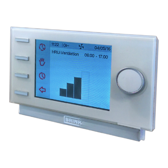
Manual control key Bypassing the timer programme 11.2 Image overview display Flow rate indicator eBus connection indicator Fan indicator Fault symbol Filter message Current time block Current time Current date (day/ month/ year) Brink Air Control 614884-A Brink / 27... -
Page 28: Image Ventilation Modes
11.3 Image ventilation modes 11.4 Image disconnecting operational module 11.5 Image electrical connection Brink Air Control 614884-A... -
Page 29: Image Wall Bracket
11.6 Image wall bracket 11.7 Image replacing operational module ± 25 seconds HRU ventilation Brink Air Control 614884-A Brink / 29... -
Page 30: Image Filter Notification
11.8 Image filter notification 11.9 Image main menu display Main menu Device information Basic settings Installer Brink Air Control 614884-A... -
Page 31: Image Resetting Filter
11.10 Image resetting filter = Filter notification = 5 seconds Brink Air Control 614884-A Brink / 31... -
Page 32: Image Device Information Menu
11.11 Image device information menu Device information HRU-appliance Information HRU ventilation Brink Air Control 614884-A... -
Page 33: Image Basic Settings
11.12 Image basic settings Basic settings Language English Brink Air Control 614884-A Brink / 33... -
Page 34: Image Installer Menu
11.13 Image installer menu Installer Airflow 30 m HRU-appliance Factory setting Device settings Please wait: Loading data Settings are reset to factory setting Airflow-mode 1 Brink Air Control 614884-A... - Page 35 Brink Climate Systems BV E info@brinkclimatesystems.com P.O. Box 11 NL-7950AA Staphorst www.brinkclimatesystems.com T +31 (0) 522 46 99 44 www.brinkairforlife.com...
Need help?
Do you have a question about the Air Control and is the answer not in the manual?
Questions and answers