Table of Contents
Advertisement
950-0027-01, Rev. B English
950-0027-01B
Synergy
Instructions for Use
HD3
The Arthrex Synergy
Camera Head User's Guide provides important
information for the safe operation of all components of the
HD3
Synergy
Camera System, including accessories. Read
this User's Guide thoroughly prior to using this system
and keep it in an easily accessible place for use by all
operating personnel. Read and follow all safety warnings,
cautions and precautions.
Arthrex, Inc.
1370 Creekside Blvd.
Naples, FL 34108, USA
+1 (800) 934-4404
Technical Support
1-800 391-8599
HD3
System
System Camera Controller and
EC
REP
Arthrex GmbH
Erwin-Hielscher-Strasse 9
81249 München, Germany
+49 89 909005-0
1 of 55
Advertisement
Table of Contents

Summary of Contents for Arthrex SynergyHD3
- Page 1 950-0027-01, Rev. B English Synergy System Instructions for Use The Arthrex Synergy System Camera Controller and Camera Head User’s Guide provides important information for the safe operation of all components of the Synergy Camera System, including accessories. Read this User’s Guide thoroughly prior to using this system and keep it in an easily accessible place for use by all operating personnel.
- Page 2 Arthrex. Arthrex reserves the right to revise this publication and to make changes from time to time in the contents hereof without obligation to notify any person of such revision or changes, unless otherwise required by law.
-
Page 3: Table Of Contents
Table of Contents Introduction ............................ 4 Intended Use ........................4 Contraindications ........................4 Warnings and Precautions ....................4 Symbol Definitions ......................9 End of Life, Environmental Directives ................. 11 Initial Use of the Device ..................... 11 Unpacking and Inspecting the Device ................. 12 Returning the Device ......................13 System Indicators ...................... -
Page 4: Introduction
It is recommended that personnel study this NOTE carry special meanings and they should manual before attempting to operate, clean, be read carefully. and/or sterilize the Arthrex Synergy System and accessories. The safe and WARNING: The safety and/or health effective use of this equipment requires the... - Page 5 Arthrex Synergy video system be burns. Always keep the light source in the maintained, sterilized, and ready to be STANDBY mode when not in use.
- Page 6 2. Do not use the camera with incompatible Avoid prolonged exposure to intense equipment or accessories that are not illumination. authorized by Arthrex. Doing so may void Use the minimum level of illumination certifications and/or warranties. necessary to satisfactorily illuminate the 3.
- Page 7 Representative. If it is necessary to return proper operation. Visually inspect lenses to the camera head to Arthrex for service, assure there are no scratches, chips or disinfect the camera head before shipping cracks.
- Page 8 16. Any person who connects external (c) Connect the equipment into an outlet on equipment to signal input and signal output a circuit different from that to which the ports or other connectors has formed a other devices are connected. system and is therefore responsible for the (d) Consult the manufacturer or field service system to comply with the requirements of...
-
Page 9: Symbol Definitions
Symbol Definitions Safety Sign Caution: Federal Law Restricts this Follow Operating device to sale by or Instructions on the order of a Physician. Power Standby/On Not for use in the Presence of Flammable Anesthetics. Attention, Consult Fragile Accompanying Documents Precaution of This Side Up Warning Notice Type BF... - Page 10 Equipotential Universal Serial [Equipment Potential] WEEE [Waste RF Symbol. Non- Electronics and ionizing Electrical Electromagnetic Equipment] Radiation Symbol. Regarding European Union End-of-Life of Product. White Balance Color Video Symbol Camera Catalog Number Serial Number Manufacturer Authorized Representative in the European Community Do Not Use if Package is...
-
Page 11: End Of Life, Environmental Directives
Control Unit and the patient. Camera endoscopic video equipment at the end of its Control Unit is intended to be used useful life for recycling, please contact Arthrex outside the Patient Vicinity. Customer Service Department. 6. Additional peripheral equipment... -
Page 12: Unpacking And Inspecting The Device
Controller Unit (CCU) and accessories. Ensure contents are complete and are free from damage. If any damage is noted contact your Arthrex Customer Service. Contact the Manufacturer for Return Authorization PRIOR to shipping your device for service. Save ALL packaging materials; they may be needed to verify any claims of damage by the shipper. -
Page 13: Returning The Device
Please make sure that all Cleaning and Sterilization prior required information has been supplied. Call to returning for service. Camera Arthrex for a RMA Number for the device return Head shall be clearly labeled as for service. “Sterile.”... -
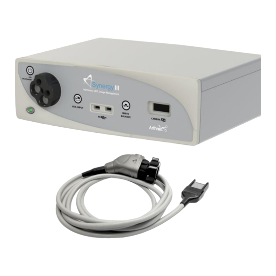
Page 14: System Indicators
Figure 1- Synergy Front Panel [AR-3200-0001T] System Indicators 6. Light Source On/Standby Switch — The Light Source On/Standby Switch toggles 1.9.1 Synergy Front Panel the Light Source between ON [Operational Mode], and STANDBY. 1. On/Standby Switch — The On/Standby switch toggles the (CCU) between ON PRECAUTION: [operational mode], and STANDBY. - Page 15 Figure 2- Synergy Rear Panel potentials between different metal parts of 1.9.2 Rear Panel various Medical Electrical [ME] equipment which make up a Medical 1. “DVI” Video Output Connectors — Electrical system, or to reduce differences of Supplies a digital video signal output in DVI- potential which can occur during operation D format.
- Page 16 Figure 3-AR-3210-0001 3 CCD Camera Head with Integrated Optics 1.9.3 AR-3210-0001 Camera Head with Integrated Optics 1. Button 1 — A programmable button 3. Focus Ring — Used to sharpen, or that can activate various functions of the camera. See “Optional Tablet Data Input bring into focus, the image detail.
- Page 17 Figure 4-AR-3210-0003 [C-MT], AR-3210-0004 [C-MT, 20 Foot Figure 5-AR-3210-0007 [C-MT, Zero Angle] 1.9.4 C-Mount Camera Heads 2. Button 2 — A programmable button 1. Button 1 — A programmable button that can activate various functions of the that can activate various functions of the camera.
-
Page 18: System Installation And Operation With Data Input Device
1. Your Synergy Camera Control Unit will 7. Insert the card edge connector the indicate which software configuration is SynergyHD3 camera head into the camera enabled at boot up, on the Video Monitor’s receptacle on the front of the console. Splash screen. -
Page 19: Accessories For Intended Use
Typical Interconnect Diagram With OPTIONAL Tablet Data Input Device Accessories for Intended Use Arthrex Synergy System Accessories Part Number Description AR-3200-1008 SynergyHD3 Digital Documentation Tablet,12" AR-3200-1014 SynergyHD3 Digital Documentation Tablet SONY UP-PR80MD Medical Grade Printers SONY UP-PR80MD with upDR80MD/NKIT Medical Grade Surgical Monitor 26”... -
Page 20: System Setup Facility And Surgeon Settings
C-Mount Optical Zoom Coupler AR-3210-1005 Video Input/Output Converter System Setup Facility and Surgeon Settings NOTE: Facility, surgeon, and procedural settings are made from the SynergyHD3’s tablet Data Input Device. Figure 7-System Maintenance 2.3.1 System Set-Up can be accessed by pressing the Maintenance Icon on the Tablet Data Input Device and then selecting “Advanced Settings”... - Page 21 Figure 8-System Maintenance Screen Selecting “System” button enables several facility preferences to be setup; 2.3.2 “Remote Entry” enables users that have networked the Synergy system to add patients from a networked computer. “Password Access” can be set to on or off. On will require a password in order to enter add patients remotely.
- Page 22 Figure 9-System Maintenance Print Fields Selecting “Print Fields” allows facilities preferences to be setup for the fields that will be 2.3.3 included on a print. Available Fields are; Facility Name Surgeon Name Patient Name Patient I.D.# ...
- Page 23 Figure 10-System Maintenance Network Selecting “Network” allows for connecting the Synergy 2.3.4 system to a facility network. Fields are: Ethernet IP Mode Host Name Ethernet IP Address Ethernet Subnet Mask Ethernet Default Gateway 23 of 55 950-0027-01B...
- Page 24 Figure 11-Surgeon Management List 2.3.5 Surgeons can be added to the Synergy with their own system preferences. 2.3.6 To add surgeons and their preferences, press the maintenance icon on the Synergy Tablet Data Input Device and then select Surgeon Management. A list of surgeons will appear.
- Page 25 Figure 12-Surgeon Management Preferences 25 of 55 950-0027-01B...
- Page 26 Figure 13-Surgeon Preferences Settings 2.3.8 Surgeon preferences can be defined for the following: Camera Settings (including camera head button setup) Printer Settings Print Fields Multimedia Web Server Access Display 26 of 55 950-0027-01B...
- Page 27 Figure 14-Surgeon Management Procedures Select 2.3.9 Procedure preferences can be added to individual surgeon preferences. On the surgeon management list, select a surgeon, and a list of procedures will appear 2.3.10 Select the appropriate Procedure for the Surgeon. If the procedure is not currently in the list, select the “Create New Procedure”...
- Page 28 Figure 15-Surgeon Preferences Camera Settings After entering Procedure Name, select “Camera Settings”. Surgeon preferences may be 2.3.11 entered for: Brightness Zoom Scene Gain Auto Exposure Window Enhancement NOTE: If a surgeon performs multiple types of procedures and it is necessary to add additional procedures, press the “Add Procedure”...
-
Page 29: Scheduling And Starting Cases
Scheduling and Starting Cases Figure 16-Scheduling a case To schedule a case, press the “+ Add New Case” icon 2.4.1 29 of 55 950-0027-01B... - Page 30 Figure 17-Scheduling a Case Select the “Surgeon” and/or “Procedure,” and enter data in the following required fields. 2.4.2 Patient First Name Patient Last Name Patient I.D. # Press the “Save” icon 2.4.3 30 of 55 950-0027-01B...
- Page 31 Figure 18-Starting a Case To start a case, select the case/patient from the Case List and press the “Start” icon 2.4.4 NOTE: Cases may also be started from the “Add Case” screen by entering the required fields and pressing the “Start” icon. 31 of 55 950-0027-01B...
- Page 32 Figure 19-Camera Head Button Change; During Case Changes to SETTINGS may be made during the procedure by pressing the “Maintenance 2.4.5 Icon”. Changes may be made to the following: Camera Head Button Functions Camera Settings Print Settings 32 of 55 950-0027-01B...
- Page 33 Figure 20-Camera Change; During Case Figure 21-Print Changes; During Case 33 of 55 950-0027-01B...
- Page 34 Figure 22-Ending a case Ending a Case; to end a case, press the “End Case” Icon. 2.4.6 NOTE: An “End Case” confirmation message will appear. If confirmed, the case will end and the Synergy Tablet Data Input Device will transition to the case review screen. 34 of 55 950-0027-01B...
-
Page 35: System Operation Without Tablet Data Input Device
2. The camera will take approximately 30- System Operation without Tablet 40 seconds to fully load its boot Data Input Device software. When the software has fully loaded you will see the Synergy Initial 1. Connect the Synergy System per Screen shown below in Figure 23 “Typical System Installation”, Figure 6. - Page 36 12. The Surgical monitor will display one of the following. When the White Balance has been completed successfully, a Green Check Mark with WHITE BALANCE below will be shown on screen. Figure 25-White Balance Fail 13. If the White Balance Operation has been successful, the camera will enter the Surgical Ready Mode and be ready for surgical operation.
-
Page 37: Picture In Picture Operation
Picture in Picture Operation Figure 26-Picture in Picture System Set Up Figure 27-Tablet PIP Control 37 of 55 950-0027-01B... - Page 38 2.6.1 The Synergy HD3 Camera Control Unit [AR-3200-0001T] can be used in the Picture in Picture Mode to display a Picture in Picture [PIP] on the surgical monitor. Second video source for PIP is connected to the Camera Controller’s DVI 2.6.2 Input.
-
Page 39: Maintenance
If it becomes necessary to return the camera head to Arthrex for service, please sterilize the camera head before shipping. - Page 40 If the camera head is dented or damaged, or if the connector jacket is cut, DO NOT autoclave or immerse in liquid (water, chemical disinfectants or sterilants, etc.). Notify your Arthrex Sales Representative. Do not place the camera head or accessories in an ultrasonic cleaner or washer/sterilizer.
- Page 41 9. CAUTION: Inspect the camera head cable for breaks and cuts. Camera heads with damaged cables should not be sterilized or disinfected. Return camera heads with damaged cables to Arthrex for repair. 10. Before sterilization and/or disinfection, coil the camera head cable into loops at least six inches in diameter.
-
Page 42: Troubleshooting
3.3.4 Material Compatibilities In addition to the Sterilization chemicals listed above, the AR-3210 camera heads are Material Compatible with Cidex OPA. No SAL claims are made with Cidex OPA. WARNING: Use of Sterilants or Chemicals other than those listed in the Cleaning and Sterilization section may result in the compromise of the device’s safety and effectiveness. - Page 43 Suspect camera head and/or camera head and/or cable cable. were faulty, return them to Camera head cable Arthrex for repair. Insert camera head cable connector not inserted correctly or completely. connector completely into the console’s camera head receptacle on the front panel.
-
Page 44: Recommended Annual Camera Control Unit Maintenance Requirements
Recommended Annual Camera Control Unit Maintenance Requirements Table 2: Recommended Annual Camera Control Unit Maintenance Requirements Test Type Test Value ZG < 100 mOhm from the ground pin on the power inlet module Ground Impedance to the Camera Control Unit’s exposed metal parts. * IL <... -
Page 45: Technical Information
Technical Information NOTE: Technical data is subject to modification, revision and improvement without notice. Table 3: Safety, EMC and Regulatory Requirements Parameter Parameter Value FDA Class Class II EU Class Class I System Classification Health Canada Class Class II UL 60601-1:2003 Domestic Certification ... - Page 46 Table 4: Safety, Classifications Classification of Equipment Parameter Value According to protection against electric shock. Class I [Grounded] According to degree of protection against Applied part is Type BF electric shock. Camera Control Units are Ordinary [IPX-0] no protection. According to Degree of protection against harmful ingress of water.
- Page 47 Parameter Parameter Value AR-3210-0001 Approximately: 18.7 ounces Camera Head Weight C-MT Heads Approximately: 16 ounces Ambient Temperature: -40°F to 122°F [-40°C to 50°C] Transport & Storage Relative Humidity: 10% to 90%, non-condensing Conditions Atmospheric Pressure: 500 hPa to 1060 hPa Ambient Temperature: +50°F to 95°F [10°C to 35°C] Operating Conditions...
-
Page 48: Appendix [Detailed Emc Information]
disturbing other Equipment and Systems or APPENDIX [Detailed non-medical electrical equipment. EMC Information] NOTE: Medical Electrical Equipment needs special precautions regarding EMC and needs DETAILED EMC INFORMATION to be installed and put into service according to the EMC information provided in the NOTE: CE marked equipment has been tested Accompanying Documents. - Page 49 Guidance and manufacturer’s declaration – electromagnetic emissions The Arthrex HD3 Video System is intended for use in the electromagnetic environment specified below. The customer or the user of the Arthrex HD3 Video System should assure that it is used in such an environment. Emissions Test...
- Page 50 Guidance and manufacturer’s declaration – electromagnetic immunity The ARTHREX HD3Video System is intended for use in the electromagnetic environment specified below. The customer or user of the ARTHREX HD3 Video System should assure that it is used in such an environment.
- Page 51 IEC 60601-1-2 Table 4 Guidance and manufacturer’s declaration – electromagnetic immunity The ARTHREX HD3 is intended for use in the electromagnetic environment specified below. The customer or user of the ARTHREX HD3 should assure that it is used in such an environment.
- Page 52 Recommended separation distances between portable and mobile RF communications equipment and the ARTHREX HD3 Video System The ARTHREX HD3 Video System is intended for use in an electromagnetic environment in which radiated RF disturbances are controlled. The customer or the user of the ARTHREX HD3 Video System can help prevent...
-
Page 53: Appendix [Sw Version Access]
3. Tap About APPENDIX [SW Version access] ACCESS to SW Version on Synergy HD3 1. Login to the Android application Figure 30-Tap ABOUT 4. Tablet and CCU software version are displayed Figure 28-Logging on to Android 2. Tap and hold the date field to bring up the Admin Options Figure 31-SW Version Information Figure 29-Tap and Hold DATE FIELD... - Page 54 THIS PAGE INTENTIONALLY LEFT BLANK 54 of 55 950-0027-01B...
- Page 55 Naples, FL 37108-1945 USA Customer Service +1 (800) 934-4404 Arthrex, Inc. Toll-Free Technical Support: 1-(800) 391-8599 Monday through Friday, 8:00 AM – 8:00 PM ET www.arthrex.com Arthrex GmbH Erwin-Hielscher-Strasse 9 81249 München, Germany +49 89 909005-0 All rights reserved. Printed in USA.
Need help?
Do you have a question about the SynergyHD3 and is the answer not in the manual?
Questions and answers