Advertisement
Quick Links
Advertisement

Subscribe to Our Youtube Channel
Summary of Contents for Hydrotec HYDROWELL Compact E Series
- Page 1 Operating and Maintenance Manual ® HYDROWELL Compact E Serial number: _____________________ HYDROTEC UK Ltd Hydrotec House Telephone: 01494 796040 5 Manor Courtyard, Hughenden Avenue Fax: 01494 796049 High Wycombe, Bucks. HP13 5RE Website: www.hydrotec.co.uk www.hydroteccontracts.co.uk...
- Page 2 Index In the following overview you find all individual chapters listed. You will find detailed information on respective first pages of the chapters. Page number Preface Chapter General Information Chapter System Description / Technical Data Chapter Installation and Assembly Chapter UV Monitor / Decommissioning Chapter Inspection and Maintenance...
-
Page 3: Preface
For any further information or if you are confronted with any problems, please contact our service and technical staff. Contact Hydrotec (UK) Ltd Hydrotec House 5 Manor Courtyard, Hughenden Avenue High Wycombe, Bucks HP13 5RE Tel.: 01494 796 040 Fax: 01494 796 049 email: services@hydrotec.co.uk... - Page 4 Please call us to arrange your free commissioning within 6 months of shipping. Hydrotec (UK) Ltd Hydrotec House 5 Manor Courtyard, Hughenden Avenue High Wycombe, Bucks HP13 5RE Tel: 01494 796040 Fax: 01494 796049 www.hydrotec.co.uk...
- Page 5 NOTE! A Hydrotec technician will make all connections between the control box and reactor and supply UV lamps when the system is commissioned. If the unit is to be connected to a BMS panel, this responsibility installation technician. Connections to BMS can be found within this manual in the wiring diagram.
- Page 6 UV light can burn skin; protective clothing should be worn at all times. Always switch the unit off at the control panel before removing lamp. The UV should only be inspected by trained technician. For sales or technical support please contact Hydrotec (UK) Ltd for more information. Hydrotec (UK) Ltd...
-
Page 7: Chapter I General Information
Chapter I General Information / Terms 1. Structure of this manual You can find all important information for the operator of this system including: • Safety information • Technical data • Information and instructions for: assembly start-up operation maintenance trouble shooting The operation and maintenance manual together with all other technical information and documents must always be kept readily accessible. - Page 8 2. Safety information 2.1. General safety instructions All declared safety instructions must be absolutely observed to prevent an endangerment of persons, environment and the system itself. The following warning signs are included in this manual: Warning signs: Danger! Adverse health effects or property damage may occur in case of non- compliance! Electric voltage! Safety signs:...
- Page 9 2.2. Operator’s duty of care The system is constructed and manufactured with respect to and in consideration of all current standards as well as further technical specifications, and corresponds to the latest state-of-the-art technology, allowing for maximum safety under all operating conditions. System safety in operation can only be assured if all necessary measures are taken beforehand.
- Page 10 2.4. Basic safety measures Prior to starting the system it must be ensured that: no one can suffer injury due to the system operation all safety facilities are in a perfectly serviceable condition The system must be operated in good condition only. All faults must be notified to the person responsible immediately after being noticed.
- Page 11 Start-up after maintenance and repair work Check screw connections for tight fit Ensure that any components removed beforehand are installed and restored to their correct operational position It is to be ensured that all materials, tools and other appliances which were necessary for maintenance and repair work are removed from the working area of the system Any liquid that has leaked is to be removed Ensure that all safety equipment is in a perfectly serviceable condition...
- Page 12 2.5. Risks in the event of safety instructions being disregarded The consequences of disregarding safety instructions can be dangerous to the system, material and personnel, and the loss of any warranty claims. We shall accept no liability for possible water damage caused due to disregard of the safety instructions.
- Page 13 - The system is treated properly - Repair work is to be carried out exclusively by authorised specialists - Original spare parts or parts recommended by Hydrotec (UK) Ltd shall be used exclusively - No modifications are carried out on the system by users themselves...
-
Page 14: Chapter Ii System Description / Technical Data
Chapter II System Description / Technical Data UV systems ® For disinfection of the water supplies a UV system should be installed. Ideally the HydroWELL units should be located in the incoming water main or after the site booster pump set where water storage tanks are employed. - Page 15 Technical Data Type ® ® ® ® HydroWELL HydroWELL HydroWELL HydroWELL Compact 2E Compact 5E Compact 10E Compact 10E (7/16000) WRAS Approval Flow rate at: 1.25 2.00 2.57 400 J/m (40 mJ/cm ) [l/s] 1.12 1.75 3.62 300 J/m (30 mJ/cm ) [l/s] 1.28 4.14...
- Page 16 Reactor Dimensional drawing with parameters from technical data sheet P a g e 16 | 38...
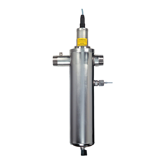
- Page 17 Connection mains supply Vent screw Lamp head Water inlet Water outlet UV sensor Housing made of stainless steel Drain tap P a g e 17 | 38...
- Page 18 Control Box UV monitor Power switch ON / OFF Cable fittings P a g e 18 | 38...
-
Page 19: Chapter Iii Installation And Assembly
Chapter III Installation & Assembly Installation Vertical installation of the UV housing vessel (in the horizontal pipeline) must be observed. Water isolation valves should be fitted either side of the unit. If site require continuous water supply to the building during maintenance works and no down time is required, then a suitable by-pass should be fitted. - Page 20 The related control must be mounted on a wall or a rigid surface. It shall be mounted on eye level and next to the reactor, within the reach of cables provided. A permanent power connection via a switchable fused spur (230V/1pH/50Hz; 5A) must be provided in close vicinity to the system. ATTENTION: Electrical connections must only be done by an authorised expert according to VDE requirements! All works must be done only by authorised and instructed experts.
- Page 21 Chapter IV UV Monitor / Taking out of Service 1. Operation of UV monitor PRO 11 1.1. Features • Measuring of UV intensity by means of a digital sensor (value shown in %) • Internal status display LCD; monitoring of UV value and operating hours additional status information by different colours of display light •...
- Page 22 1.2. Key functions UV – MONITOR 100% Keys ‘Up’ and ‘Down’ Hours: Key ‘Enter’ PRO 11 • ‘Enter’ ( enter configuration menu skip menu item confirm parameter • ‘Up’ (Up arrow key) show software version increase value change option • ‘Down’...
- Page 23 1.4. Messages and Indications Main alarm indicated via display and BMS relay Display and relay show normal operation 1.4.1. “Max. lifetime – replace lamp” Possible reason: • Lamp lifetime is exceeded Display is flashing red/yellow -> relay indicate normal operation Meaning: •...
- Page 24 Attention: Electrical connection and commissioning shall only be executed by an authorised expert according to VDE regulations! Attention: Protect your eyes and skin against UV light. UV light is causing strong sunburn and painful conjunctivitis. Activate UV lamp only after it has been already inserted into the reactor, never before! A safe operation of system is ensured through indication of the UV intensity.
- Page 25 3. Thermostatic Purge Valve In case of the continuous water flow through the unit not being guaranteed at all times, it is highly recommended that a thermostatic purge system is installed with the UV unit. This is to protect the UV unit from overheating.
-
Page 26: Chapter V Inspection And Maintenance
Chapter V Inspection & Maintenance 1. Inspection by the operator For the safe operation of your UV disinfection system a regular inspection for possible damages, leakages and other anomalies is to be performed for all parts of the system. We recommend to check the following operating parameters at least within the predefined intervals and to keep them on the record in an operating logbook (see Appendices 6). - Page 27 Electrical works must only be executed by authorised experts according to VDE regulations! For queries regarding operation and handling of UV disinfection system, please contact our service department: Hydrotec (UK) Ltd Hydrotec House Manor Courtyard, Hughenden Avenue High Wycombe, Bucks HP13 5RE Tel: 01494 796 040 Email: services@hydrotec.co.uk...
- Page 28 UV intensity and thus to a fault in the system. Typical deposits consist of lime scale or iron and can be removed with a commercial acid cleaning agent. Please call Hydrotec Services Department regarding any Services related issues. Hydrotec (UK) Ltd Hydrotec House...
- Page 29 Quartz tube insert for Compact 10E 300.080 For queries regarding operation and handling of UV disinfection system as well as any spare part enquiry, please contact our services department: Hydrotec (UK) Ltd Hydrotec House Manor Courtyard, Hughenden Avenue High Wycombe, Bucks HP13 5RE Tel: 01494 796 040 email: services@hydrotec.co.uk...
-
Page 30: Appendices 1 Installation Schematics
Appendices 1: Installation Schematic UV Disinfection System P a g e 30 | 38... -
Page 31: Appendices 2 Wiring Diagram
Appendices 2: ® Wiring diagram HydroWELL 2 E, 5 E and 10 E with sensor P a g e 31 | 38... - Page 32 ® Wiring diagram HydroWELL 10E (7/16000) with sensor Outputs: 1 x Power supply sensor 12V DC, max. 25mA 1 x Potential-free output 4 - 20mA; Rmax = 200Ω; Signal is assigned to measured value of the UV intensity 20mA = 100% 1 x Relay main alarm 50 - 500mA, 24V - 230V AC;...
- Page 33 Appendices 3: Start-up and Instruction Record ® HydroWELL System size / Serial number: _________________________________________________ Customer: _________________________________________________ ◼ Correct installation: ◼ Isolation valves provided on both sides: (for Service) ◼ Are the connections water tight? ◼...
- Page 34 Appendices 4: ® Log Book UV Disinfection System HydroWELL Site: ______________________________________________________________ Time period: ______________________________________________________________ Total Relative UV intensity Water meter Date Signature operating hours operating hours in % reading in m³ P a g e 34 | 38...
- Page 35 ® Log Book UV Disinfection System HydroWELL Site: ______________________________________________________________ Time period: ______________________________________________________________ Total Relative UV intensity Water meter Date Signature operating hours operating hours in % reading in m³ P a g e 35 | 38...
- Page 36 Please complete & Sign this form and fax to HYDROTEC to arrange commissioning of your HydroWELL ® Water Disinfection Unit on FAX: 01494 796 049 or Email: services@hydrotec.co.uk Name Site Contact Company Company Address Site Address Full Postcode Full Postcode...
- Page 37 E-P – AL / EK All rights reserved! © 07/2019 by HYDROTEC Subject to technical modification! All information, dimensions and sketches correspond to the latest state of technique at date of that document. Modifications that suit the technical progress and development of the product are reserved.
Need help?
Do you have a question about the HYDROWELL Compact E Series and is the answer not in the manual?
Questions and answers