Table of Contents
Advertisement
Quick Links
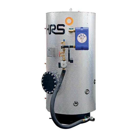
HRS AQUASAVE
6 bar Storage – 600 to 2,000 Litres
Operating & Instruction Manual
A60B
No Controls
6
Bar Range
A62B
2 Port Control
Head Office
10-12 Caxton Way, Watford.
WD18 8JY t. 01923 232335
mail@hrs.co.uk
3 Port Control
North & Factory
No 1 Rosemount Works, Elland
HX5 0EE t. 01422 317070
www.hrshevac.co.uk
A63B
A63B
Advertisement
Table of Contents

Summary of Contents for HRS AQUASAVE A6 Series
- Page 1 HRS AQUASAVE Bar Range 6 bar Storage – 600 to 2,000 Litres Operating & Instruction Manual A60B A63B A63B No Controls 3 Port Control A62B 2 Port Control Head Office North & Factory 10-12 Caxton Way, Watford. No 1 Rosemount Works, Elland WD18 8JY t.
- Page 2 HRS Hevac Ltd AquaSave A6 Range Installation, Operating & Instruction Manual AquaSave A60B Dimensional Details Primary Inlet 2 Primary Outlet 3 Secondary Flow 4 Secondary Return 5 Cold Feed 6 Instrument Connections (3-off) 7 Gauge Connections A60B 8 Immersion Heater(s) - See Table...
-
Page 3: Table Of Contents
HRS Hevac Ltd AquaSave A6 Range Installation, Operating & Instruction Manual Contents Product overview ........................5 Working pressure and temperature ......................6 Packing format ............................6 Options ..........................7 A60B No Controls ................................7 Port Control Valve ........ - Page 4 20.1.1 Electrical wiring ..........................55 20.1.2 Wiring diagram ..........................55 Commissioning report......................56 Declaration of Conformity ....................57 Warranty ..........................58 23.1 Spare parts ............................. 58 23.2 How to contact HRS Hevac ........................58 4 of 58 www.hrshevac.co.uk 01923 232335...
-
Page 5: Product Overview
HRS Hevac Ltd AquaSave A6 Range Installation, Operating & Instruction Manual Product overview The basic version of the HRS Hevac AquaSave DHW heater, indirect (semi-instantaneous) system comprises: A60B A62B A63B No Controls 2 Port Control 3 Port Control Storage tank, stainless steel storage tank... -
Page 6: Working Pressure And Temperature
HRS Hevac Ltd AquaSave A6 Range Installation, Operating & Instruction Manual Working pressure and temperature PRIMARY SIDE SECONDARY SIDE AquaSave Max working Max working Model Type Max temperature (°C) Max temperature (°C) pressure (bar) pressure (bar) A60B A62B A63B Packing format... -
Page 7: Options
HRS Hevac Ltd AquaSave A6 Range Installation, Operating & Instruction Manual Options There are three different control systems available as option. A60B - No Controls Supplied with only the secondary charging circuit. Follow the assembly instructions in 17 Assembly of the charging kit to the AquaSTOR... -
Page 8: A63B 3 Port Control Valve
HRS Hevac Ltd AquaSave A6 Range Installation, Operating & Instruction Manual A63B - 3 Port Control Valve One 3-port control valve, PN16 One primary shunt pump, PN10 One actuator, 24V AC feed-in and 0-10V DC controller current One PID controller box with Pt100 temperature sensor... -
Page 9: Installation
HRS Hevac Ltd AquaSave A6 Range Installation, Operating & Instruction Manual Installation Siting The AquaSave hot water heater shall be installed in a dry place where room temperature is below 40°C, and ideally in ventilated premises. AquaSave is placed preferably on a sub-base footing. -
Page 10: Commissioning
HRS Hevac Ltd AquaSave A6 Range Installation, Operating & Instruction Manual Bottom section connection, shut-off valve inserted between the conduit hose and the cold water inlet fixture. Commissioning Flood the various circuits and flush-bleed the pumps. Power-up. Set the secondary (charging) flow rate using the setting valve (read-off + setting) NOTE: When first heated, the water in the tank will expand, increasing the pressure. -
Page 11: Setting The Dhw Flow Rate
HRS Hevac Ltd AquaSave A6 Range Installation, Operating & Instruction Manual Setting the DHW flow rate The secondary DHW flow rate is set with the tank full and the primary circuit at nominal operating temperature and at the available exchanger power capacity required for the generator. -
Page 12: Electrical Connections
HRS Hevac Ltd AquaSave A6 Range Installation, Operating & Instruction Manual Electrical connections All devices shall be connected up in compliance with the governing standards. All work on control box and other electrical components must be done by qualified people. -
Page 13: Electrical Installation Of Control Box, A62B & A63 Only
HRS Hevac Ltd AquaSave A6 Range Installation, Operating & Instruction Manual Electrical installation of control box, A62B & A63B only Power supply the control box with 230VAC 50 Hz. The control box with the controller Micro 3000 is called the secondary control box. -
Page 14: Electrical Wiring Diagram A62B
HRS Hevac Ltd AquaSave A6 Range Installation, Operating & Instruction Manual Electrical wiring diagram A62B NOTE: When the remote control contact is open, the unit operates normally. If it is closed the unit is in standby. NOTE: *) 230V 3pts actuator wiring, see 20 Special instructions for options. -
Page 15: Electrical Wiring Diagram A63B
HRS Hevac Ltd AquaSave A6 Range Installation, Operating & Instruction Manual Electrical wiring diagram A63B NOTE: When the remote control contact is open, the unit operates normally. If it is closed the unit is in standby. www.hrshevac.co.uk 15 of 58... -
Page 16: User Instruction Operator Control Panel Micro 3000
HRS Hevac Ltd AquaSave A6 Range Installation, Operating & Instruction Manual User instruction operator control panel Micro 3000 Button Function Rotary button, wheel, for scrolling through the menus. Access sub-menus and change settings by pressing it. To activate the line or change a highlighted value, simply press the wheel. -
Page 17: Home Screen
HRS Hevac Ltd AquaSave A6 Range Installation, Operating & Instruction Manual Home screen When starting up the Micro 3000 controller this menu displays on them screen. The menu is called the Home screen. Date / hour Access level: Locked=restricted /... -
Page 18: Setting The Time And Date
HRS Hevac Ltd AquaSave A6 Range Installation, Operating & Instruction Manual Setting the time and date 1. Turn the wheel anticlockwise to highlight the line with time and date at the top of the screen. Press the wheel to enter the Date/Time menu. -
Page 19: End User Mode
Please set a hot water production temperature in line with current national legislation and recommendations (UTD, Standards EN, ISO etc.) All countries have different rules for how hot or cold tap water should be. HRS Hevac recommends the hot water temperature is at least 55°C and a hot water recirculation not less than 50°C. -
Page 20: Changing Time And Temperature In A Time Program
HRS Hevac Ltd AquaSave A6 Range Installation, Operating & Instruction Manual Changing time and temperature in a time program By default the DHW set point SP_T_Sec_Outlet, set to 60°C by default, at any time, all the days of the week. -
Page 21: Making A Quick Temperature Change
HRS Hevac Ltd AquaSave A6 Range Installation, Operating & Instruction Manual Making a quick temperature change It is possible to quickly define a “one time” temperature change, a period of the day with a different setting. When the change period has expired, the temperature set point goes back to standard time schedule program. -
Page 22: Technician Menu
HRS Hevac Ltd AquaSave A6 Range Installation, Operating & Instruction Manual Technician menu In the technician menu you can: make settings for the secondary outlet temperature enable/disable functions like Eco, booster, thermal treatment change parameters start an auto test clear alarm. -
Page 23: Configuration Menu
HRS Hevac Ltd AquaSave A6 Range Installation, Operating & Instruction Manual Configuration menu NOTE: After resetting the controller, this sub menu should be accessed to configure pumps’ number. Parameter Factory Optional setting Description Setting Type 0= First 1=Eff 0= AquaFirst... -
Page 24: S1 Menu Secondary Outlet
HRS Hevac Ltd AquaSave A6 Range Installation, Operating & Instruction Manual S1 Menu Secondary Outlet Parameter Factory Optional setting Description Default Setting SP_T_Sec_Outlet 60°C DHW Setpoint Change setpoint value in clock program Delta T S1 HiAlm 10°C 0-50 High Temperature Alarm if Ts1... -
Page 25: Safety Function
HRS Hevac Ltd AquaSave A6 Range Installation, Operating & Instruction Manual Safety Function This function activates all the pumps' power relays at the same time without considering ipsothermic contacts' inputs. NOTE: This function can be enabled from end user level. -
Page 26: Fouling Function
HRS Hevac Ltd AquaSave A6 Range Installation, Operating & Instruction Manual Fouling function Accessing the scaling-menu requires login at Technician level. Scaling function can be activated when the sensor S3 is connected. If the temperature in S3 is too high for a long time this function activates an alarm that consider the heat exchanger fouled. -
Page 27: Autotest Menu
HRS Hevac Ltd AquaSave A6 Range Installation, Operating & Instruction Manual 9.10 Autotest menu Accessing the Autotest menu requires login at Technician level. This submenu allows testing analog (contacts) and digital (0-10V) outputs that manage pumps start/stop, both programmable relays, 230V Triac output and valve’ signal. It is possible to run an automatic sequence or to test manually each output individually. -
Page 28: Clear Alarm Menu
HRS Hevac Ltd AquaSave A6 Range Installation, Operating & Instruction Manual NOTE ! Once test is manually done and finished, remember to put the point on Automatic mode, logo The Auto test sekvens described in the picture is a general test procedure. It may vary depending on connected components. -
Page 29: Service Menu
HRS Hevac Ltd AquaSave A6 Range Installation, Operating & Instruction Manual Service Menu Press the key to enter the Service menu. In the service menu you can: change password for technician level trending parameters display the trend buffer check operating hours From Point Data sub-menu you can, read or change binary or analog outputs to start/stop a pump, open/close control valve for example. -
Page 30: Menu Continue
HRS Hevac Ltd AquaSave A6 Range Installation, Operating & Instruction Manual 10.3 Menu Continue Menu Sub-menu Sub-menu Description Continue Operating hours Viewing operating hours of internal parameters Trending Points in trend Select variables to trend for example temperature sensors Display Trend buffer... -
Page 31: Operating Hours
HRS Hevac Ltd AquaSave A6 Range Installation, Operating & Instruction Manual 10.4 Operating hours Operating hours for the following parameters can be checked: Therm_Protec_P1 /P3 AFF_leg_active Cmd_P1/P3 SAFETY_FCT High_Temp_Alarm Multi P Main_Alarm For more information and descriptions see 12 Parameters’... -
Page 32: Trending Parameters Menu
HRS Hevac Ltd AquaSave A6 Range Installation, Operating & Instruction Manual 10.5 Trending parameters menu A lot of different variables can be recorded or trended. It can be temperatures’ measurement, valves or pumps’ signals, ipsothermic contacts, alarms, thermal treatments etc. -
Page 33: Display The Trend Buffer
HRS Hevac Ltd AquaSave A6 Range Installation, Operating & Instruction Manual 10.6 Display the trend buffer 1. Press key to access to Service Menu, then click on “Continue”. 2. Select “Trending” in the menu. 3. Select “Display Trend Buffer”. 4. Select the variable to display, S1 in this case, and press the wheel. -
Page 34: Alarm Menu
HRS Hevac Ltd AquaSave A6 Range Installation, Operating & Instruction Manual Alarm menu Alarm indication is a volt Free Contacts (VFCs), 2 Amps maxi, each under 230 V. Press key to access to Alarm menu. The menu contains four different lists: Alarm Buffer Lists all events with;... -
Page 35: Parameters' List
HRS Hevac Ltd AquaSave A6 Range Installation, Operating & Instruction Manual Parameters’ list There are more than 100 different parameters used in the controller. Most of them are used for internal programs and calculations. Here we describe the main points. -
Page 36: Factory Reset
HRS Hevac Ltd AquaSave A6 Range Installation, Operating & Instruction Manual Factory reset After a reset must the controller be configured, 9.3 Configuration menu. Especially the number of pumps must be configured. 1. Press both for 5 seconds. 2. Rotate the wheel; select the last line, program name with a star at the end. -
Page 37: Modbus
HRS Hevac Ltd AquaSave A6 Range Installation, Operating & Instruction Manual Modbus 14.1 Modbus communication The controller includes a Modbus slave communication protocol, type Modbus RTU RS485. Connection between BMS (building management system) and Micro 3000 requires two polarized wires on C+ and C-, respectively labelled 25 and 26 on controller C Bus terminal. -
Page 38: Change Modbus Parameters
HRS Hevac Ltd AquaSave A6 Range Installation, Operating & Instruction Manual 14.3 Change Modbus parameters 1. Press key to access to Service Menu, go to “Login Installer”, press the wheel. 2. Enter the current password, press the wheel to validate. -
Page 39: Modbus Slave Communication Parameters
HRS Hevac Ltd AquaSave A6 Range Installation, Operating & Instruction Manual 14.4 Modbus slave communication parameters www.hrshevac.co.uk 39 of 58 01923 232335... -
Page 40: Trouble Shooting
HRS Hevac Ltd AquaSave A6 Range Installation, Operating & Instruction Manual Trouble shooting FINDINGS PROBABLE CAUSES REMEDIES Pump not operating Locked rotor or damaged Force to rotate. Replace if required Corresponding led is not lit Replace Power Board Pump relay damaged... -
Page 41: Maintenance And Repairs
HRS Hevac Ltd AquaSave A6 Range Installation, Operating & Instruction Manual Maintenance and repairs HRS Hevac AquaSave does not require any specific maintenance. The frequency of the inspections depends on the water hardness, temperature and flow rate. Weekly inspections: Check for leaks on pipes and components. -
Page 42: Antibacterial Treatment Of The Aquastor
HRS Hevac Ltd AquaSave A6 Range Installation, Operating & Instruction Manual 16.1 Antibacterial treatment of the AquaSTOR Clean and disinfect the system at least once a year Whenever the AquaSTOR or exchanger circuits are to be drained, it is crucial to let the water cool down to preclude any risk of scolding or burns. -
Page 43: Clean The Copper Brazed Plate Heat Exchangers
HRS Hevac Ltd AquaSave A6 Range Installation, Operating & Instruction Manual 16.2 Clean the brazed plate heat exchangers Only the specially designed, pre-fitted cleaning kit and compatible agents should be used for cleaning brazed plate heat exchangers. Protective gloves and glasses should always be worn while these operations Use the specially-engineered plugs and isolate the secondary circuit using the gate valves. -
Page 44: Open The Control Box
HRS Hevac Ltd AquaSave A6 Range Installation, Operating & Instruction Manual 16.3 Open the control box Remove the front panel by turning the lock button counter clockwise and lift up the cover. Unscrew the two screws in bottom and lift up the panel. -
Page 45: Set The Number Of Pumps
HRS Hevac Ltd AquaSave A6 Range Installation, Operating & Instruction Manual 16.5 Set the number of pumps The pumps’ configuration and connections is factory made. In a servicing situation the correct pump must be identified. Codification Meaning Connected pump(s) A62B... -
Page 46: Assembly Of The Charging Kit To The Aquastor
HRS Hevac Ltd AquaSave A6 Range Installation, Operating & Instruction Manual Assembly of the charging kit to the AquaSTOR NOTE: The photos are non-binding – changes are liable to made without notice. 1. Unpack secondary charging kit and 2. Tools required to install the secondary check all parts for damage. - Page 47 HRS Hevac Ltd AquaSave A6 Range Installation, Operating & Instruction Manual Mount the heat exchanger on the support Tighten the “U” bracket on the heat bracket and connect to the secondary exchanger support. isolation valve. 8. Connect the secondary inlet sub-assembly connection of the heat exchanger.
- Page 48 HRS Hevac Ltd AquaSave A6 Range Installation, Operating & Instruction Manual 11. Connect the exible hose to the 10. Install a fibre washer in to one end of secondary pump. the exible hose. 12. Insure the pump connection is tight.
-
Page 49: Attaching The Heat Exchanger Insulation
HRS Hevac Ltd AquaSave A6 Range Installation, Operating & Instruction Manual 15. Mount the first half of the insulation 16. Mount the second half of the insulation jacket, aligning with the heat exchanger jacket, aligning with the heat exchanger secondary connections. -
Page 50: Wiring The Seconary Shunt Pump
HRS Hevac Ltd AquaSave A6 Range Installation, Operating & Instruction Manual 19. Remove the secondary pump terminal 20. Attach the gland and wiring loom to box cover. the terminal box. 21. Remove the protective terminal strip 22. Connect the secondary pump wiring. -
Page 51: Flowcharts
HRS Hevac Ltd AquaSave A6 Range Installation, Operating & Instruction Manual Flowcharts 18.1 Flowchart A60B HRS Hevac Scope of Supply Heat Exchanger 1 Primary Inlet Isolating Valve 2 Primary Outlet Shunt Pump 3 Cold Feed Flow Regulating Valve 4 Water Outlets Secondary Buffer Vessel www.hrshevac.co.uk... -
Page 52: Flowchart A62B
HRS Hevac Ltd AquaSave A6 Range Installation, Operating & Instruction Manual 18.2 Flowchart A62B HRS Hevac Scope of Supply Heat Exchanger 1 Primary Inlet 2 Port Control Valve 2 Primary Outlet Control Panel 3 Cold Feed 4 Water Outlets Control Sensor... -
Page 53: Flowchart A63B
HRS Hevac Ltd AquaSave A6 Range Installation, Operating & Instruction Manual 18.3 Flowchart A63B HRS Hevac Scope of Supply Heat Exchanger 1 Primary Inlet Primary Shunt Pump 2 Primary Outlet 3 Port Control Valve 3 Cold Feed 4 Water Outlets... -
Page 54: Wiring The Charging Pump
HRS Hevac Ltd AquaSave A6 Range Installation, Operating & Instruction Manual Wiring the charging pump Note: The charging pump has not been wired previous to delivery. The five wires cable connected to the control box that must be wire to the charging pump. -
Page 55: Special Instructions For Options
HRS Hevac Ltd AquaSave A6 Range Installation, Operating & Instruction Manual Special instructions for options 20.1 Special instructions for A62B The actuator has been factory-calibrated. No special setting is needed. 20.1.1 Electrical wiring Wire terminal 20.1.2 Wiring diagram www.hrshevac.co.uk 55 of 58... -
Page 56: Commissioning Report
HRS Hevac Ltd AquaSave A6 Range Installation, Operating & Instruction Manual Commissioning report All parts are not applicable to the AquaSave 56 of 58 www.hrshevac.co.uk 01923 232335... -
Page 57: Declaration Of Conformity
HRS Hevac Ltd AquaSave A6 Range Installation, Operating & Instruction Manual Declaration of Conformity www.hrshevac.co.uk 57 of 58 01923 232335... -
Page 58: Warranty
Non-payment will lead to all operational warranties covering the delivered equipment being terminated. 23.1 Spare parts Only replace any defective part with the original spare part. Please contact HRS Hevac during the warranty period. 23.2 How to contact HRS Hevac Hevac Limited mail@hrshevac.co.uk www.hrshevac.co.uk...
Need help?
Do you have a question about the AQUASAVE A6 Series and is the answer not in the manual?
Questions and answers