
Summary of Contents for Brooks Polycold MaxCool Series
- Page 1 ® Polycold MaxCool Cryochiller Installation and Operation Manual Including Models: MaxCool 4000H MaxCool 2500L 214072 Revision B...
- Page 2 © 2014 Brooks Automation, Inc. All Rights Reserved. The information included in this manual is Proprietary Information of Brooks Automation and is provided for the use of Brooks Automation customers only and cannot be used for distribution, reproduction, or sale without the express written permission of Brooks Automation. This information may be incorporated into the user’s documentation, however any changes made by the user to this...
-
Page 3: Table Of Contents
Thermal Hazards .............2-15 Brooks Automation... - Page 4 Install Cajon VCR Couplings (Optional Fitting) ....... 4-25 Brooks Automation...
- Page 5 24V DI/DO Remote Installation ..........5-24 Brooks Automation...
- Page 6 Commonly Used Host Commands ..........7-8 Brooks Automation...
- Page 7 Circuit Operational State Commands ..........7-36 Brooks Automation...
- Page 8 Date or Time Troubleshooting ......... . . 10-9 Brooks Automation...
- Page 9 Contact Brooks Information........
- Page 10 Contents Polycold Cryochiller Installation and Operation Manual This Page Intentionally Left Blank Brooks Automation 214072 Revision B...
-
Page 11: Introduction
This manual provides information for a wide variety of Polycold Cryochiller configurations. Some of the features that are shown are optional and may not be installed on your system. Refer to Brooks Automa- tion sales literature to determine what items are optional. -
Page 12: System Illustration
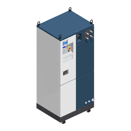
Lines Feed (left) Return (right) EMO Switch (optional) (optional) Circuit 2 Refrigerant Display Lines Feed (left) Keypad Return (right) Communications Panel Circuit Breakers Power In Water In / Out Figure 1-1: Illustration of MaxCool Cryochiller Brooks Automation 214072 Revision B... -
Page 13: System Summary
The innovative cryogenic refrigeration process in the Polycold Cryochiller uses patented refrigerant mixtures and patented control processes developed by Brooks Automation Polycold Systems. Some configurations include advanced controls that reduce power consumption. Models are available that control two independent circuits, providing greater design flexibility for vacuum systems such as two cryocoils or one cryocoil and one cryobaffle. -
Page 14: Polycold Cryochiller Versions
The Polycold Cryochiller is manufactured in different models and configurations to fit a variety of appli- cations. Table 1-1 shows the currently manufactured Cryochiller model numbers and their description. Contact Brooks Sales for optional configurations. Table 1-1: Polycold Cryochiller Models and Descriptions Configuration Description... -
Page 15: Water Vapor Capturing In High Vacuum Systems
The cryocoil is easy to install and can be adapted to fit any system. It does not need a high vacuum valve. See Figure 1-3 on page 1-6. Brooks Automation 214072 Revision B... -
Page 16: Minimizing Oil Backstreaming From Diffusion Pumps
See Figure 1-4 on page 1-7. Optically transparent cryobaffles are also available from Brooks Automation Polycold. These baffles are appropriate for increased water vapor pumping speed in turbomolecular pump applications. Brooks Automation... -
Page 17: Heat Removal
See Figure 1-5. Brooks Automation 214072 Revision B... -
Page 18: Polycold Cryochiller System Components
Polycold Cryochiller components are shown along with all optional components. Optional components must be selected when the system is ordered. Polycold Cryochiller Component List See figures 1-2, 1-3, and 1-4. 1. Human Machine Interface - HMI - Area 2. Fan Filter Access Brooks Automation 214072 Revision B... - Page 19 17. Lifting Rings (4 Places) (Optional) 18. Remote Interface Terminals 19. Thermocouple Access Panel 20. Discharge Service Valve 21. Compressor 22. Expansion Tank (s) 23. Pressure Gauge 24. Profibus Connection (Optional) 25. Thermocouple Terminal Block Brooks Automation 214072 Revision B...
-
Page 20: Polycold Cryochiller Views
Introduction Polycold Cryochiller Polycold Cryochiller System Components Installation and Operation Manual Polycold Cryochiller Views Figure 1-6: Polycold MaxCool Cryochiller System Exploded View Brooks Automation 1-10 214072 Revision B... - Page 21 Polycold Cryochiller Introduction Installation and Operation Manual Polycold Cryochiller System Components Figure 1-7: Polycold MaxCool Cryochiller Compressor View Brooks Automation 1-11 214072 Revision B...
- Page 22 Figure 1-8: Low Voltage Section Limitations This product is intended for use by industrial customers and should be serviced only by Brooks or Brooks trained representatives. The Installation and Operation manual and related materials are provided in English at no charge and are intended for use by experienced technicians.
-
Page 23: Regulatory Compliance
The Polycold Cryochiller meets the requirements of the European Union’s Machinery Directive (2006/42/EC), the Low Voltage Directive (2006/95/EC), and the EMC Directive (2004/108/EC). Brooks Automation has issued a Declaration of Conformity for units that are used independently from a system, and the Polycold Cryochiller has a CE mark affixed. -
Page 24: Declaration Of Incorporation (Doi)
Business name and full address of the manufacturer of the partly completed machinery: Brooks Automation Inc., 15 Elizabeth Drive, Chelmsford, MA, USA 01824 Name and address of the person, established in the Community, authorized to compile the relevant technical documentation:... -
Page 25: Disclosure Table, Eip
Polycold Cryochiller Introduction Installation and Operation Manual Regulatory Compliance Disclosure Table, EIP Brooks Automation 1-15 214072 Revision B... -
Page 26: Limited Warranty
SERIAL NUMBER HAS BEEN ALTERED, DEFACED OR REMOVED, THE USE OF SERVICE REPLACEMENT REFRIGERANTS FROM ANY THIRD PARTY NOT LICENSED BY BROOKS, OR THE PRODUCT IS OTHERWISE COMPROMISED BY USE OF UNAUTHOR- IZED PARTS OR SERVICE, ALL AS DETERMINED BY BROOKS IN ITS SOLE DISCRETION. -
Page 27: Safety
Read and understand each procedure before performing it. If additional safety related upgrades or newly identified hazards associated with the Polycold Cryo- chiller are identified, Brooks Automation Technical Support notifies the owner of record with a Technical Support Bulletin (TSB). -
Page 28: Signal Words And Color
A note does not use icons. The following is an example of a Note. NOTE: Save all shipping materials for future use. If the Polycold Cryochiller is shipped, the original shipping crate must be used. Brooks Automation 214072 Revision B... -
Page 29: General Guidelines
Product. • Only Brooks parts are authorized to be used when configuring or repairing this system. Proper Operation Improper use of the Polycold Cryochiller may cause personal injury. -
Page 30: Safety Labels And Safety Label Identification
Figure 2-2 shows the location of each label. To replace a lost or damaged label call Brooks Automation Technical Support. Table 2-1: Labels Used on the Polycold Cryochiller... - Page 31 How to avoid the hazard: Do not touch exposed piping. Allow to come to ambient temperature before servicing. Unit Nameplate Label, Abbreviated Part Number: 179924 Qty: 1 Location: Outside Lower Right Front Cover Contains part number, serial number Brooks Automation 214072 Revision B...
- Page 32 Table 2-1: Labels Used on the Polycold Cryochiller Nameplate Label Part Number: 407168-00 (left or top section) Qty: 1 (2 label set) Location: Inside on lower left frame of compressor area Contains part number, serial number, and specification information. Brooks Automation 214072 Revision B...
- Page 33 Safety Labels and Safety Label Identification Table 2-1: Labels Used on the Polycold Cryochiller Nameplate Label Part Number: 407168-00 (right or bottom section) Qty: 1 (2 label set) Location: Inside on lower left frame of compressor area Contains specification information Brooks Automation 214072 Revision B...
- Page 34 Safety Polycold Cryochiller Safety Labels and Safety Label Identification Installation and Operation Manual 407114-00 407110-00 407112-00 184193 407168 407114-00 Figure 2-2: Locations of Labels on the front side of the Polycold Cryochiller Brooks Automation 214072 Revision B...
-
Page 35: Safety And Operational Interlocks
Cryochiller by the user. For additional information, see Compres- sor Safety Chain on page 6-7. The Cryochiller contains the interlocks listed in Table 2-2 and shown in Figure 2-4. Brooks Automation 214072 Revision B... - Page 36 Do not defeat, modify, or disable any of the unit’s safety inter- locks. NOTICE The user may choose to add an Emergency Off (EMO) circuit to the Polycold Cryochiller and is accountable for that EMO circuit. Brooks Automation 2-10 214072 Revision B...
- Page 37 All energy must be removed from the equipment per the sys- tem’s or the facility’s Lockout/Tagout procedure before servicing. • If local procedures are not available, follow the procedure for Lockout/Tagout in OSHA Standard 29CFR 1910.147. Brooks Automation 2-11 214072 Revision B...
-
Page 38: Cryochiller Lockout/Tagout
For uneven or soft floors, move using optional hoist rings with overhead lift • Do not use casters to move up and down ramps. • Apply force below center line when moving by hand. • Lock two front casters when not moving. Brooks Automation 2-12 214072 Revision B... - Page 39 The Polycold Cryochiller weighs a minimum of 533 kg (1175 lb) up to a maximum of 544 kg (1200 lb). Failure to take the proper precautions before moving this unit could result in personal injury. • Follow appropriate methods for moving heavy equipment. Brooks Automation 2-13 214072 Revision B...
-
Page 40: Electrical Hazards
Installation and Operation Manual Electrical Hazards The Brooks Automation Polycold Cryochiller is a hazardous voltage device. It requires a user installed slow blow circuit breaker that meets, or exceeds, the minimum SCCR rating specified by SEMI S2. See Electrical on page 3-4. -
Page 41: Thermal Hazards
Moving or repositioning the refrigerant line when cold may result in crimping of the gas lines and insulation may crack and cause minor or moderate injury along with hazardous refrigerant discharge. • Do not attempt to move or position the refrigerant line. Brooks Automation 2-15 214072 Revision B... -
Page 42: Chemical Hazards
(Type 2, High Pressure) perform any procedure that could release refrigerant to the atmosphere. This includes: • Installing the Polycold Cryochiller • Inspecting procedures • Disconnecting the refrigerant lines • Troubleshooting procedures • Repairing • Disposing of the unit or charged components Brooks Automation 2-16 214072 Revision B... -
Page 43: High Pressure Gas Hazard
• The vacuum chamber must have a pressure-relief valve to avoid an over-pressure condition. Brooks Automation 2-17 214072 Revision B... -
Page 44: Environmental Information
The compressor in the Polycold Cryochiller contains lubrication oil which may be considered a hazard- ous substance. The MSDS for the POE Solest LT-32 oil is included in Appendix J: Material Safety Data Sheets - MSDS on page 12-21 Brooks Automation 2-18 214072 Revision B... -
Page 45: Specifications And Site Preparation
Sound measurements were made on each side of the unit at a distance of 1.0m (39 in) and at a height of 1.6m (63 in). Measurements taken from each side of the unit did not vary sig- nificantly. Measurements will vary with the acoustics of the environment. Brooks Automation 214072 Revision B... -
Page 46: Dimensions
For a unit with casters, increase vertical dimension by 76.2mm (3 inches) For a unit with lift hooks folded down, increase vertical dimension by 34mm (1.34 inches) Designates Center of Gravity Figure 3-1: Polycold Cryochiller Refrigeration Unit Dimensions Brooks Automation 214072 Revision B... -
Page 47: Site Preparation
Multiple units may be placed side by side as long as the rear clearance is provided. Figure 3-2: Polycold Cryochiller Service Access Multiple units placed facing each other Units are mm (inches) (not to scale) require 914mm (36 inches) front service access. Brooks Automation 214072 Revision B... -
Page 48: Electrical
380-3-50 342-418 @ 50 Hz 400-3-50 400-3-50 360-440 @ 50 Hz 415-3-50 380-480 VAC 440-3-60 460-3-60 414-506 @ 60 Hz 460-3-60 480-3-60 480-3-60 432-528 @ 60 Hz 575 VAC 575-3-60 575-3-60 518-632 @ 60 Hz Brooks Automation 214072 Revision B... -
Page 49: Electrical Protection Requirements - Maxcool 4000H And 2500L
Compressors are provided with over current and over temperature protection which comply with UL and NEC definitions of inherent thermal protection. kVA = (Test Volts) X (RLA) X (1.732/1000) kW = (kVA) X Power Factor (Power Factor is 90% in this case.) Brooks Automation 214072 Revision B... -
Page 50: Cooling Water
38 (100) – Max. 77.2 (11.2) 3.4 (0.15) 21.7 (74,109) NOTE: Pressure Drop values assume a 3/4-inch (20 mm) standard pipe size. Maximum working pressure of the unit’s cooling water circuit is 1380 kPa (200 psig). Brooks Automation 214072 Revision B... -
Page 51: Cooling Water Purity
Larger particles can clog heat exchanger passages. Lower levels increase corrosion risk Higher levels increase scale formation and precipitation. 7.5 - 9.0 Some references recommend keeping the pH level in the range 7.5 – 8.5 Brooks Automation 214072 Revision B... - Page 52 Higher turbidity levels are signs of high levels of microorganisms. Turbidity < 5 FTU Clean water is less likely to form deposits. Ammonium (NH < 2 ppm Higher levels increase the risk of copper corrosion. Brooks Automation 214072 Revision B...
-
Page 53: Performance Specifications
Installation and Operation Manual Performance Specifications Performance Specifications Table 3-8 lists the performance specifications for the Polycold Cryochiller product family. For additional information, contact Brooks Automation Polycold Systems. Table 3-8: Typical Performance Specifications Performance MaxCool 4000H MaxCool 2500L Maximum load... -
Page 54: Cryocoils And Refrigerant Lines
The heat gain through the insulation on the combined feed and return refrigerant line set is 8 Watts/ft (25 Watts/m). The cryocoil(s) must be specified and sized for the process. Contact Brooks Automation Polycold for assistance in selecting the proper cryocoil. -
Page 55: Balance Pressure
It is the balance of pressure on both sides, the suction side and the discharge side, of the compressor. When the compressor is running, the unit creates a pressure difference between the suction and discharge sides of the compressor. Brooks Automation 3-11 214072 Revision B... -
Page 56: Refrigerants In The Maxcool Unit
Refrigerants used in the Blend Model Blend GWP Weight - kg (lb) (see product I.D. Label for amounts) MaxCool 4000H R-245fa, R-125, R-23, R-14, Argon 8.5 (18.74) 5310 MaxCool 2500L R-245fa, R-125, R-23, R-14, Argon 9.0 (19.9) 5200 Brooks Automation 3-12 214072 Revision B... -
Page 57: Installation
Confirm the availability of certified refrigeration specialists that may be required for some pro- cedures. • Arrange for a qualified electrician or electrical installer to perform electrical power installation. • Follow the Installation Checklist to guide you through the installation. Brooks Automation 214072 Revision B... -
Page 58: Installation Checklist
Connect the Refrigerant Line Thermocouples 4-36 Preliminary Check of the Polycold Cryochiller 4-39 Insulate Exposed Refrigerant Tubes and Couplings 4-41 Startup and Test 4-46 Evaluate the Polycold Cryochiller / Place Into Service 4-48 Install Seismic Restraints (as required) 4-51 Brooks Automation 214072 Revision B... -
Page 59: Installation Overview
• Brooks determined the refrigerant safety group classification of the refrigerant mixture by eval- uating the safety group classifications of the individual components. This evaluation used ANSI / ASHRAE-34 and EN 378.1 as a guide. -
Page 60: Inspect And Unpack The Polycold Cryochiller
• Review this manual before performing any procedure. This includes routine operation of the Polycold Cryochiller. • Know the information in the Safety Chapter. • Review the MSDSs that are associated with this tool. Brooks Automation 214072 Revision B... - Page 61 Do NOT install a damaged unit. Notify Brooks Automation of the damage to the unit. • Arrange with the carrier and Brooks Automation to repair the damage or replace the unit. Refer to the Brooks Automation contact information in the Appendix of this manual. •...
- Page 62 24 hours to stabilize to the new room temperature before reading the balance pressure and verifying correct charge pres- sure. e. If the pressure is not within the listed range, contact the nearest Brooks Automation Poly- cold Service Center. NOTE: If the system is exposed to extreme cold during shipping, the balance pressure is reduced due to the increased condensation of the refrigerant mixture.
-
Page 63: Move To Location
Wear gloves and goggles when working around the Polycold Cryochiller. 1. Check the location where the Cryochiller is to be placed. Refer to Figure 3-1 on page 3-2 Figure 3-2 on page 3-3 for placement and spacing requirements. Brooks Automation 214072 Revision B... - Page 64 4. Keep the Cryochiller vertical while it is being moved. 5. Place the refrigeration unit at the desired location. 6. Go to the Installation Checklist Table 4-1. Initial and date this task. Go to the next checklist task. Brooks Automation 214072 Revision B...
-
Page 65: Remove The Compressor Hold-Down Nuts
Remove the spare parts kit and verify that all of the parts were shipped with the unit. 4. Locate the compressor in the bottom of the refrigeration unit. See Figure 4-3 Figure 4-5. Figure 4-4: Rear Lower Panel Access Screws Figure 4-3: Polycold Cryochiller with panels removed showing compressor location Brooks Automation 214072 Revision B... -
Page 66: Connect The Cooling Water
NOTICE Water should be filtered for contaminants and copper reducing microbes. Brooks recommends filtration to 100 microns and microbiological controls be put in place in order to supply clean and safe cooling water to your Polycold product. Failure to provide water of proper specification may void the system warranty. - Page 67 Manual Filters shut-off valves Water from Water to IN water port facilities on refrigeration unit Flow Meters Figure 4-6: Redundant Water Circuits in Supply Line, Optional Brooks Automation 214072 Revision B 4-11...
- Page 68 7. When the water connections are installed, test, and do not leak, go to the Installation Checklist Table 4-1 on page 4-2. Initial and date this task. Go to the next task on the checklist. Brooks Automation 4-12 214072 Revision B...
-
Page 69: Connect Electrical Power
If using 4-conductor cable that is too stiff to bend in the cable tracks, remove the outer jacket from the cable after it passes through the strain relief. Optionally, use Terminal Block Accessory and Wir- ing Kt, p/n 181500. Brooks Automation 214072 Revision B 4-13... - Page 70 / input side of CB1 using the provided screws and washers (optional) in the stack sequence shown Ground Figure 4-10. Conductor Figure 4-9: Input Power Connections to CB1 Brooks Automation 4-14 214072 Revision B...
- Page 71 “Excepted Wiring Method” as found in Appendix C: CB2 Excepted Wiring on page 12-5 or contact Brooks as required. 14. Check the input voltage and compare to the voltage specified on the system label. Adjust the tap settings, if required, to accommodate the actual input voltage.
-
Page 72: Input Power Transformers
Replace the protective cover Figure 4-12: Tap Settings for 230 and 480 Volt Transformers 4. Go to the Installation Checklist Table 4-1. Initial and date this task. Go to next task on the checklist. Brooks Automation 4-16 214072 Revision B... -
Page 73: Install The Cryosurface
Cryocoils and Refrigerant Lines on page 3-10. The feed-through on the Brooks Polycold Systems Cryocoil is designed to be installed from the inside of a vacuum chamber. This allows removal of the cryosurface when cleaning or servicing the vacuum chamber. - Page 74 10. Check the vacuum chamber for leaks. If any leaks are found, correct them before proceeding. 11. Go to the Installation Checklist Table 4-1. Initial and date this task. Go to the next task on the check- list. Brooks Automation 4-18 214072 Revision B...
-
Page 75: Install A Cryobaffle
Initial and date this task. Go to the next task on the checklist. Install the Refrigerant Lines NOTICE This procedure assumes that refrigerant lines from Brooks Automation, Inc. Polycold Systems are being installed. • If installing a refrigerant lines not made by Polycold Systems, verify that the refrigerant lines meet the required specifications. -
Page 76: Guidelines For Refrigerant Lines
Use of unauthorized or non-standard couplings voids your warranty. Improper use of, incorrect installation of, over-tightening of, or use of damaged O-rings in couplings will void your warranty. NOTICE O-ring removal tool requires lubrication. Always clean couplings after using the lubricated tool. Brooks Automation 4-20 214072 Revision B... -
Page 77: Route And Install The Refrigerant Lines
Brooks Automation. Inc. Polycold Systems recommends using a continuous line length from the refrigerant unit to cryocoil feed-through. Polycold does not recommend or warranty the use of intermediate fittings. - Page 78 Scratches • Dents 3. Clean the sealing surfaces of the couplings. If the sealing surfaces are scratched or dented, contact the Brooks Automation Polycold Service Department. NOTE: Parker UltraSeal compatible couplings are standard on all Polycold Cryochillers. 4. Connect the refrigerant line to the cryosurface first, if possible.
- Page 79 Continuous escape of refrigerant is NOT OK. Quickly reinstall the blank-off fit- tings and make certain the isolation valves are closed. Circuit 1 Feed Return Lines Lines Circuit 2 Figure 4-16: Polycold Cryochiller Refrigerant Lines with Standard Ultra Fittings Brooks Automation 214072 Revision B 4-23...
-
Page 80: Install Parker Ultraseal Compatible Couplings (Standard Fitting)
4. Use two wrenches to tighten the coupling. Keep the male coupling stationary with the 15/16-inch wrench and tighten the nut with the 1-inch wrench. Each wrench must have a length of at least 12 inches (300 mm). Brooks Automation 4-24 214072 Revision B... -
Page 81: Install Cajon Vcr Couplings (Optional Fitting)
Torque values are pro- vided for customers requiring a measurable value. 4. Go to Installation Checklist Table 4-1. Initial and date this task. Go to the next task on the checklist. Brooks Automation 214072 Revision B 4-25... -
Page 82: Route Condensate Drain Tube
5. Route the tubing to a facility waste water drain or to the input line of a condensate pump. External Condensate Drain Tube Figure 4-20: Condensate Drain Tube 6. Go to the Installation Checklist Table 4-1. Initial and date this task. Go to the next task on the check- list. Brooks Automation 4-26 214072 Revision B... -
Page 83: Check The Refrigerant Line And Cryosurface For Leaks
If helium is used as a leak check medium, only use helium while the compressor is off and ensure that the pressure in the line and cryosurface during this test does not exceed the lowest refrigerant pres- Brooks Automation 214072 Revision B... -
Page 84: Leak Check Procedure
4. Connect the refrigerant cylinder to the center port of the manifold. 5. Open the suction valve on the manifold and pressurize the refrigerant line and cryosurface to 70-140 kPa (10-20 psig). This adds refrigerant trace gas to the system. Brooks Automation 4-28 214072 Revision B... - Page 85 If there is a large leak and the source cannot be pinpointed without activating the leak detector, open the manifold's suction valve until the pressure drops to about 345 kPa (50 psig). This should allow detection of the source of the leak. Brooks Automation 214072 Revision B 4-29...
- Page 86 4-31. • To correct a a leak on a brazed joint or a valve, contact Brooks Service for assistance. 13. If no leaks are found, verify the manifold pressure is still 1030kPa (150 psig). 14. If the pressure in the manifold stays at 1030 kPa (150 psig), follow these steps: a.
-
Page 87: Correct A Leak In A Parker Ultraseal Compatible Or Cajon Vcr Coupling
Cajon VCR Couplings (Optional Fitting) on page 4-25. e. Leak check the coupling again. • If the coupling still leaks, contact Brooks Automation Service. • If the leak is repaired, return to the previous procedure. 3. Return to the Check Refrigerant Lines procedure. -
Page 88: Evacuate The Refrigerant Line And Cryosurface
Have a qualified refrigeration technician do all refrigerant work. 1. Connect the vacuum pump, vacuum gauge, and service manifold. See Figure 4-24. Figure 4-24: Cold Valve Box Setup to Evacuate Refrigerant Line and Cryosurface Brooks Automation 4-32 214072 Revision B... - Page 89 VLV6 in the warm valve assembly. • Dual Circuit: VLV5, VLV11 in the cold valve box VLV6 and VLV12 in the warm valve assembly. VLV5 Cool Ckt 1 VLV11 Cool Ckt 2 Figure 4-25: Cold Valve Box Brooks Automation 214072 Revision B 4-33...
- Page 90 5. Allow the vacuum pump to continue pumping for at least 30 minutes. NOTE: The vacuum pump should evacuate the refrigerant line and cryosurface to 13Pa (0.1 torr) within 30 minutes. If not, there may be a leak which must be corrected. Brooks Automation 4-34 214072 Revision B...
- Page 91 It is very important to re-install the protective cap and flare nut with bonnet onto the evacuation valve to prevent refrigerant leaks. 9. Go to the Installation Checklist Table 4-1 on page 4-2. Initial and date this task. Go to the next task. Brooks Automation 214072 Revision B 4-35...
-
Page 92: Connect The Refrigerant Line Thermocouples (Type T)
Custom 1 (customer use, no control functions) Optional TC18 Custom 2 (customer use, no control functions) Optional TC19 Custom 3 (customer use, no control functions) Optional TC20 Custom 4 (customer use, no control functions) Optional Brooks Automation 4-36 214072 Revision B... - Page 93 Then, pass the wires behind the interface panel and to the thermocouple terminal block. 3. Locate the external thermocouple terminal block in the low voltage box. See Figure 4-29 Brooks Automation 214072 Revision B 4-37...
- Page 94 Additional Thermocouples can be added by the user as desired. If you are working on a single circuit Polycold Cryochiller, connect the Thermocouple wires as fol- lows: • Position # 9: COIL IN • Position # 10: COIL OUT Brooks Automation 4-38 214072 Revision B...
-
Page 95: Preliminary Check Of The Polycold Cryochiller
2. Perform the following tasks before opening the isolation valves on the refrigeration unit: Refer to Figure 4-31 a. Check the Refrigerant Line and Cryosurface for Leaks b. Evacuate the Refrigerant Line and Cryosurface Brooks Automation 214072 Revision B 4-39... - Page 96 Evac Ckt 1 VLV11 * Cool Ckt 2 MV101 Hot Gas Feed MV102 Cold Gas Feed MV103 Common Return Figure 4-31: Illustration of Cold Valve Box with Valve Names * asterisk denotes optional item Brooks Automation 4-40 214072 Revision B...
-
Page 97: Insulate Exposed Refrigerant Tubes And Couplings
Initial and date this task. Go to the next task on the check- list. Insulate Exposed Refrigerant Tubes and Couplings Properly insulating the exposed tubes and couplings keeps them dry. Penetrating moisture adds heat load to the cryopump and can cause corrosion or leaks. Brooks Automation 214072 Revision B 4-41... - Page 98 1 inch to ensure there are no gaps. Alternately, cut sheet insulation the same length as the tubes of insulation and wrap the sheet once Brooks Automation 4-42 214072 Revision B...
- Page 99 Polycold Cryochiller panel. 6. Use the tape or sheet Insulation to insulate all remaining exposed tubes and refrigerant compo- nents between the refrigerant line insulation and the feed-through. Figure 4-33: Insulating Exposed Tubes and Couplings Brooks Automation 214072 Revision B 4-43...
- Page 100 Seal both ends of the insulation with tape to secure the insulation on to the insulation on the refrig- erant lines and to the feed-through. Do not put the tape closer than 1-2 inches (25-50 mm) to the threads on the feed-through. Brooks Automation 4-44 214072 Revision B...
- Page 101 Figure 4-36: View of Armaflex Insulating Tape on Refrigerant Line Bundle on Polycold Cryochiller 8. Go to the Installation Checklist Table 4-1. Initial and date this task. Go to the next task on the check- list. Brooks Automation 214072 Revision B 4-45...
-
Page 102: Startup And Test
6. On systems equipped with the EMO, twist the EMO switch clockwise to confirm that it is in the Out or disengaged position. See Figure 4-39 7. Move the compressor On/Off switch to the ON position. See Figure 4-39 The unit should go to the Standby mode. See Figure 4-40. Brooks Automation 4-46 214072 Revision B... - Page 103 17. For systems with dual refrigerant circuits, repeat steps 9 Figure 4-42: Select Cool Mode through 16 for channel 2. 18. Go to the Installation Checklist Table 4-1. Initial and date this task. Go to the next task on the check- list. Brooks Automation 214072 Revision B 4-47...
-
Page 104: Evaluate The Polycold Cryochiller / Place Into Service
Oil level should be 1/8 to 1/2 full on a compressor that has been running for at least 60 minutes. Preferred level is 1/8 full. See Figure 4-43. Record the compressor oil level after the compressor has run for at least 60 minutes. Brooks Automation 4-48 214072 Revision B... - Page 105 7. Evacuate the vacuum chamber where the cryosurface is installed to at least 0.01 torr (1.33 Pa). 8. Select Cool and wait 30 minutes. NOTE: If a dual circuit system, select Cool for both refrigerant circuits. Brooks Automation 214072 Revision B 4-49...
- Page 106 16. Record all measurements taken in this task in a maintenance log for future use as a baseline. 17. Go to Installation Checklist Table 4-1. Initial and date this task. Go to the next task on the checklist. Brooks Automation 4-50 214072 Revision B...
-
Page 107: Install Seismic Restraints
3. Secure the seismic brackets to the floor using appropriate hardware as required by the bracket design and facility or local regulations. 4. Tighten all hardware to appropriate torque specifications. 5. Go to the Installation Checklist Table 4-1. Initial and date this task. Brooks Automation 214072 Revision B 4-51... - Page 108 Installation Polycold Cryochiller Install Seismic Restraints Installation and Operation Manual This Page Intentionally Left Blank Brooks Automation 4-52 214072 Revision B...
-
Page 109: Interfacing
Low Voltage Box. The connections that are available on each unit depend on the communications options ordered with that unit. Low Voltage Box Interface Connection Panel Remote Interface Panel Figure 5-1: Interface Communication Connections Brooks Automation 214072 Revision B... -
Page 110: General Interface Rules
DB9 Female connection on Communications Panel Cable Standard RS-232 Null Modem cable with 9-pin D male connector Communication Fixed Settings Settings 9600 baud, 7 data, even parity, 1 stop bit, no hardware flow control Protocol EIA-232-E RS-232 Connection Brooks Automation 214072 Revision B... -
Page 111: Gauge Relay (J4)
1 to the current default Cool mode. Figure 5-3: Gauge Relay Connection See Gauge Relay Kit in Optional Parts on page 11-3 for the kit part number. External Vacuum Control on page 8-4. Brooks Automation 214072 Revision B... -
Page 112: Human Machine Interface - Hmi
HMI Local is not required to be active in order to browse the HMI screens. OK LED • If OK LED is lit, indicates compressor contactor is closed. (compressor on) • If OK LED is not lit, indicates compressor contactor is not closed. Brooks Automation 214072 Revision B... -
Page 113: Fault Leds
Enter at the last digit to store the value. • Display illustrations in this chapter show the full list of screen options for each nested display. Brooks Automation 214072 Revision B... -
Page 114: Hmi Home Screen Display
Static display of selected LN3 value Up to 8 user selected values from Static display if only 1LN4 value is selected. LN4 list Scrolling display of all selected LN4 values if 2 or more values are selected. Brooks Automation 214072 Revision B... -
Page 115: Hmi Top Menu
MONITOR CONFIG> SET COMM PARAMS> SET PRESSURE UNITS> DATE XX-XX-XXXX TIME XX:XX:XX SERVICE MENU Go to Basic Service XXXXXXXXX on page 5-13 XXXXXXXXX SW VER XX.XX.XX.XX DSP VER XX.XX.XX.XX CPRS HRS LAST RCHG AUTHORIZATION CODE Brooks Automation 214072 Revision B... -
Page 116: System Status
Interfacing Polycold Cryochiller HMI Display Installation and Operation Manual System Status From HMI Top Menu On Page 5-8 Brooks Automation 214072 Revision B... -
Page 117: Configuration
DEFROST COOL DEVICENET HEAT TEMP CONTROL HEAT TEMP CONTROL COOL RAMP CONTROL PROFIBUS DEFROST RAMP CNTL DFR RAMP CONTROL COOL TEMP CONTROL WEB GUI DFR RMP+TEMP CNTL DFR RMP+TEMP CNTL COOL RMP+TMP CNTL HEAT HEAT Brooks Automation 214072 Revision B... -
Page 118: Configuration Page 2
Interfacing Polycold Cryochiller HMI Display Installation and Operation Manual Configuration Page 2 From HMI Top Menu on page 5-7 See Also Configuration Go to Set Comm Parameters on page 5-12 Brooks Automation 5-10 214072 Revision B... -
Page 119: Control Parameters
STK WARM ST PT C1 DEFR COMPLT C2 DEFR COMPLT C1 BYPASS TMP C2 BYPASS TMP BUFF MIN OPEN C1 COOL RAMP LMT C2 COOL RAMP LMT C1 DEFR RAMP LMT C2 DEFR RAMP LMT Brooks Automation 5-11 214072 Revision B... -
Page 120: Set Comm Parameters
XXX.XXX.XXX.XXX NETMASK NETMASK XXX.XXX.XXX.XXX XXX.XXX.XXX.XXX MAC ID XX-XX-XX-XX-XX-XX RMT SIGNAL LOGIC OP MODE LOGIC COMP SIGNAL LOGIC ON WHEN COMP OFF COOL DEFR-STANDBY COMP CTRL OFF WHEN COMP OFF COOL DEFR-COOL NO COMP CTRL Brooks Automation 5-12 214072 Revision B... -
Page 121: Basic Service
HMI Display Basic Service From HMI Top Menu on page 5-7 SERVICE MENU XXXXX XXXXXXXXXX SW VER XX.XX.XX.XX DSP VER XX.XX.XX.XX CPRS HRS LAST RCHG NONE AUTHORIZATION CODE> AUTHORIZATION CODE 0.*.*.*.*.* Go to Service Manual Brooks Automation 5-13 214072 Revision B... -
Page 122: Ethernet
(nnn.nnn.nnn.nnn) May be left blank or all zeros Host command DEFAULT_GATEWAY HMI “Set Comm Params - Ethernet Host” Speed 10/100 Mbps Protocol IEEE 802.3 10Base-T, IEEE 802.3u 100Base-TX Ethernet Ethernet Host Service Connection Connection Figure 5-5: Ethernet Host and Ser- Brooks Automation 5-14 214072 Revision B... -
Page 123: Profibus
Profibus DP-V0 Slave Use appropriate GSD file to configure ProfiBus on host system Profibus Pass-Through Profibus Connection in Center of LV Top Panel Figure 5-6: Profibus Pass-Through and Low Voltage Box Top Panel Connection Brooks Automation 5-15 214072 Revision B... -
Page 124: Devicenet
Host command DEVICENET_PARAMS HMI “Set Comm Params” Speed (125, 250, 500 Kbps) Host command DEVICENET_PARAMS HMI “Set Comm Params” Protocol Common industrial protocol (CIP), ODVA DeviceNet specification DeviceNet Connection Figure 5-7: DeviceNet Communication Connection Brooks Automation 5-16 214072 Revision B... -
Page 125: 24V Di/Do Remote Interface
LEGACY_REMOTE,OP_MODE_LOGIC or from HMI -> Top Menu -> Configuration -> Set Comm Params -> Legacy Remote -> Op Mode Logic. • Default behavior in v1.4.0.3 is PFC backward compatible when v1.4.0.3 is installed. Users will see a change from the previous MaxCool behavior. Brooks Automation 5-17 214072 Revision B... - Page 126 Contact rating is 10A Customer must supply external relay Customer must supply 24 V AC/DC or indicator to detect the output. power which is returned by the output relay contacts when output is active. Brooks Automation 5-18 214072 Revision B...
- Page 127 24V DI/DO Remote Connector Figure 5-8: 24V DI/DO Remote Communication Connection Isolated pin sequence Non-Isolated pin sequence Female pins, wire side view Male pins, wire side view Figure 5-9: 24V DI/DO Connector Wire-Side Pin-Out Brooks Automation 5-19 214072 Revision B...
-
Page 128: 24 V Di/Do Single Circuit Non-Isolated
If a Polycold Cryochiller with the new 24V DI/DO non-isolated interface is replacing a PFC unit that used the standard PFC remote interface, please note that the Cryochiller isolated remote has some differ- ences. Please carefully review the wiring information in this section. Figure 5-10: 24V DI/DO Single Circuit Non-Isolated Brooks Automation 5-20 214072 Revision B... -
Page 129: 24 V Di/Do Dual Circuit Non-Isolated
If a Polycold Cryochiller with the new 24V DI/DO non-isolated interface is replacing a PFC unit that used the standard PFC remote interface, please note that the Cryochiller isolated remote has some differ- ences. Please carefully review the wiring information in this section. Figure 5-11: 24V DI/DO Dual Circuit Non-Isolated Brooks Automation 5-21 214072 Revision B... -
Page 130: 24 V Di/Do Single Circuit Isolated
5. Active LOW inputs and active LOW outputs - Connect +24DC at the INPUT_COMMON terminals (Pins 2, 14 and 24 of 37-Pin CPC connector) and GND signal at the OUTPUT_COMMON terminals (Pin-4, 6, 10 and 17 of 37-Pin CPC connector) Brooks Automation 5-22 214072 Revision B... -
Page 131: 24 V Di/Do Dual Circuit Isolated
5. Active LOW inputs and active LOW outputs - Connect +24DC at the INPUT_COMMON terminals (Pins 2, 14 and 24 of 37-Pin CPC connector) and GND signal at the OUTPUT_COMMON terminals (Pin-4, 6, 10 and 17 of 37-Pin CPC connector) Brooks Automation 5-23 214072 Revision B... -
Page 132: 24V Di/Do Remote Installation
The cable clamp may be reversed for large or small cables. Tinned Lead Solder Tail Shrinkable Insulating Tubing Connector Connector Cable Clamp Back Shell Wire Side Figure 5-14: 24V DI/DO Remote Solder-tail Connector Wiring (non-isolated male pins shown) Brooks Automation 5-24 214072 Revision B... -
Page 133: Operation
This chapter discusses the standard operating methods as well as other methods used for a variety of different application requirements and system configurations. Review this chapter and your application to ensure that you use the appropriate features and get the best performance from your system. Brooks Automation 214072 Revision B... -
Page 134: System Components
Display Lines Feed (left) Keypad Return (right) Communications Panel Compressor ON/OFF Switch Valve Access Panel Circuit Breakers CB1 and CB2 (CB3 behind panel) Power In Cooling Water In/Out Figure 6-1: Illustration of Polycold Cryochiller Components Brooks Automation 214072 Revision B... -
Page 135: Local Controls And Indicators
Enters the current submenu designated by > character Advances to next character in a selected field. Saves the current value after last character is selected Note: Cannot go backwards. Enter and redo if an error is created. Brooks Automation 214072 Revision B... - Page 136 Faults - General (!) Amber General LED on solid • when a general fault has occurred See HMI message Faults - Pressure (P) Red Pressure LED on solid • when high pressure fault has occurred See HMI message Brooks Automation 214072 Revision B...
-
Page 137: Led Status Table
If the Cylinder Unloader solenoid is enabled, it is activated if the unit is in Standby for more than the time designated by the command POWER_MGMT_STANDBY_DELAY. Default value is 20 minutes. E_MGMT_ENABLE is enabled by default if the system is equipped with Cylinder Unloader. Compressor will continue to run when in Standby Mode. Brooks Automation 214072 Revision B... -
Page 138: Cool
After DEFR_SETPT is reached, the valve is closed. (standard) Defrost Mode Selection Defrost modes can be selected using the HMI or the remote command line interface to set the default Defrost mode for the heat buttons. Brooks Automation 214072 Revision B... -
Page 139: Dual Circuit Modes Of Operation
One Circuit Defrost versus One Circuit Standby The cryosurface being defrosted may have a defrost time that is slightly longer than when both cryosur- faces are defrosted at the same time. Brooks Automation 214072 Revision B... -
Page 140: Compressor Safety Chain
Software “Thermal Overload” Software monitors system performance comparing suction and dis- Fault charge pressures. Generates “Thermal Overload” fault when condi- tions are met. Fault condition opens the compressor contactor. Fault resets after a 30 minute wait period. Brooks Automation 214072 Revision B... -
Page 141: Polycold Cryochiller Startup
Compressor turns on • OK LED is lit. 4. After the compressor starts, the Standby LED is on until the operating mode is changed. NOTE: Several conditions prevent compressor starting. See Compressor Motor Troubleshooting on page 10-4 Brooks Automation 214072 Revision B... -
Page 142: Operating The Polycold Cryochiller With A Cryocoil
2. By default, the unit terminates Defrost when the return temperature of the refrigerant reaches 20°C. This assures that no additional moisture condenses on the cryocoil from the atmosphere. The thermocouple and the end point temperature are user configurable if a shortened Defrost cycle is desired. Brooks Automation 6-10 214072 Revision B... -
Page 143: Operating The Polycold Cryochiller With A Cryobaffle
4. Evacuate the vacuum chamber where the cryobaffle is installed to at least 0.01 torr (1.33 Pa). 5. From Standby, select Cool and allow the cryobaffle to cool down. 6. Turn on the high vacuum pump. It is not necessary to wait until the cryobaffle has cooled down. Brooks Automation 6-11 214072 Revision B... -
Page 144: Defrost The Cryobaffle
The Defrost cycle may release the captured moisture too quickly and damage the equipment. 3. When the cryobaffle is free of moisture, return the system to Cool mode as described at the begin- ning of this procedure. Brooks Automation 6-12 214072 Revision B... -
Page 145: Host Commands
Circuit Sensor Readings Commands ..........7-37 Brooks Automation... -
Page 146: Command Format
Invalid command or invalid data argument for the given command. Set commands have min and max values associated with each command. If a set command uses a value outside the min/max range, ‘F’ is the response. Brooks Automation 214072 Revision B... -
Page 147: Command Terms
5. Look up the decimal value in the parameter list. This example shows that alarm bit 13 is set. Table 7-2: Hexadecimal Bit Field Decoding Hex Bit Hex Digit 4 Hex Digit 3 Hex Digit 2 Hex Digit 1 Hex Value Binary Value Brooks Automation 214072 Revision B... -
Page 148: Checksum Calculation
= checkSum + (pCommand[charNum] & 0x7f); charNum++; } while ( pCommand[charNum] != 0 ); checkSum = 0x3f & (checkSum ^ (checkSum >> 6) ); checkSum = (0x30 + checkSum) & 0x7f; return checkSum; }// End Function CtiChkSum Brooks Automation 214072 Revision B... -
Page 149: Excel Macro For Checksum Calculation
= (&H30 + checksum) And &H7F checksumChar = Chr(checksum) checksumstring = "CheckSum Character is: " & checksumChar Response = MsgBox(checksumstring, 0, "CheckSum Result") End Sub 5. Save the Excel program using a name you might remember such as “CheckSum Macro”. Brooks Automation 214072 Revision B... -
Page 150: Example Of Interface Usage
$SYSTEM_CONTROL_MODE,04 command to Set System Control Mode $ then command SYSTEM_CONTROL_MODE then ,0 (set to 0 local mode) then 4 (checksum) $A0 is the response for Set System Control Mode $ then response code A (accepted) then 0 (checksum) Brooks Automation 214072 Revision B... -
Page 151: Set Command Information
Normal unit access. Normal operations are available such as Cool, Defrost, Rapid BP Check. • Security Level 3 - Some Configuration / Maintenance (manager access) Contact Brooks Poly- cold for password Access to service menu for Zero Line Loss function to allow disconnect and installation. -
Page 152: Example Of Security Level
Return value: 1e70ff7f,0,23.5,23.5,23.5,171.8,171.8,171.8,121.1,0.0,171.8,171.8, 171.8,171.8,171.8,171.8,171.8,171.8,0.0,0.0,0.0,0.0,23.9,25.2, 0.0,0.0,0.0,0.0,0.0,180.6,92.0,0.0,0.0,0.0,0.0,0 SYSTEM_CONTROL_MODE Get/Set the current “Control” interface of the system (ie. RS-232, Ethernet etc. SYSTEM_CONTROL_MODE_DEF Get/Set the current default “Control” interface of the system (ie. RS-232, Ethernet etc.) Brooks Automation 214072 Revision B... -
Page 153: System Configuration Commands
Software Version & Build Number Purpose: Returns identifier strings for the current software version and build number. Parameter(s): Return Value: [A][nn.nn.nn.nn] (major.minor.patch.build) Default Value: Security Level: Get: 1 Set (none) Example: “SW_VER,?” Get application software revision Interface RS-232, Ethernet Brooks Automation 214072 Revision B... -
Page 154: Vendor_Id
? or [nnn.nnn.nnn.nnn] [nnn.nnn.nnn.nnn] is the Gateway address Return Value: [A] or [A][nnn.nnn.nnn.nnn] Default Value: 0.0.0.0 Security Level: Get: 1 Set: 3 Example: “DEFAULT_GATEWAY,192.168.1.1” Set the default gateway for host port Interface RS-232, Ethernet Brooks Automation 7-10 214072 Revision B... -
Page 155: Network_Mask
[A] or [A][speed],[Mac ID] Default Value: A,63 Min: [speed] = 0 Max: [speed] = 2 [Mac ID] = 0 [Mac ID] = 63 Security Level Get: 1 Set: 3 Example: “DEVICENET_PARAMS,?” Interface RS-232, Ethernet Brooks Automation 7-11 214072 Revision B... -
Page 156: Profibus_Params
[nnnn] is HMI timeout in seconds Return Value: [A] or [A][nnnn] Default Value: Min: 30 Max: 1800 Security Level: Get: 1 Set: 3 Example: “HMI_TIMEOUT,?” get the current HMI timeout setting Interface RS-232, Ethernet Brooks Automation 7-12 214072 Revision B... -
Page 157: Legacy_Remote,Comp_Signal_Logic
Max: [n] = 1 Units: Security Level Get: 1 Set: 3 Example: “LEGACY_REMOTE,COMP_SIGNAL_LOGIC,0” Set the Legacy Remote interface to use the state of the compressor on/off input signal to control the compressor. Interface RS-232, Ethernet Brooks Automation 7-13 214072 Revision B... -
Page 158: Legacy_Remote,Rmt_Signal_Logic
[n] = 1 Min: [n] = 0 Max: [n] = 1 Units: Security Level Get: 1 Set: 3 Example: “LEGACY_REMOTE,RMT_SIGNAL_LOGIC,0” Set the Legacy Remote, remote signal logic to the original MaxCool logic. Interface RS-232, Ethernet Brooks Automation 7-14 214072 Revision B... -
Page 159: Legacy_Remote,Op_Mode_Logic
Min: [n] = 0 Max: [n] = 1 Units: Security Level Get: 1 Set: 3 Example: “LEGACY_REMOTE,OP_MODE_LOGIC,0” Set the Legacy Remote, operat- ing mode logic to the original MaxCool operating mode logic. Interface RS-232, Ethernet Brooks Automation 7-15 214072 Revision B... -
Page 160: System Operational State Commands
8 = Default Control Mode (SYSTEM_CONTROL_MODE_DEF) Return Value: [A] or [A][n] Default Value: Determined by command SYSTEM_CONTROL_MODE_DEF Security Level Get: 1 Set: 2 Example: “SYSTEM_CONTROL_MODE,0” Set the system to local mode. Interface RS-232, Ethernet Brooks Automation 7-16 214072 Revision B... -
Page 161: Fault_Status
5: C2 OUTLET SENSOR (TC12) bit 6: C1 FEED SENSOR (TC13) bit 7: C1 RETURN SENSOR (TC3) bit 8: CLDST LQD TEMP (TC4) bit 9: C2 FEED SENSOR (TC14) bit 10: C2 RETURN SENSOR (TC5) Brooks Automation 7-17 214072 Revision B... -
Page 162: Alarm_Status
[nnnnnnnn] is a 32 bit number / bitfield that represents the state of the alarm. Displays the hex number that represents the state of the 6 bits of one of the bitfields returned by ACTIVE_ALARMS command Brooks Automation 7-18 214072 Revision B... -
Page 163: Active_Alarms
• bit 10: VOLT OUT OF RANGE • bit 11: COOLING WATER • bit 12: WATER TEMP HIGH • bit 13: PRESSURE SWITCH • bit 14: LOW SUCT PRESSURE • bit 15: THERMAL OVERLOAD Brooks Automation 7-19 214072 Revision B... - Page 164 28: OPTION3 TC FAULT • bit 29: OPTION4 TC FAULT • bit 30: Not Used • bit 31: Not Used parameter 3: Performance Monitor alarms: 32 bit number / bitfield • bit 0: Balance Pressure Brooks Automation 7-20 214072 Revision B...
- Page 165 15: Cool Down Time • bit 16: Cool Down Asymptote • bit 17: Defrost time • bit 18: Cool Steady Security Level Get: 1 Set: N/A Example: “ACTIVE_ALARMS,1,?” Get current active alarms Interface RS-232, Ethernet Brooks Automation 7-21 214072 Revision B...
-
Page 166: Capacity_Target_Temp
[nnnn] is delay in seconds Return Value: [A] or [A][nnnn] Data Type: Integer Default Value: 1200 Min: 1 Max: 36000 Units: Seconds Security Level Get: 1 Set: 3 Example: “POWER_MGMT_STANDBY_DELAY,?” Get the power management delay Interface RS-232, Ethernet Brooks Automation 7-22 214072 Revision B... -
Page 167: E_Mgmt_Enable
26: Not Used (0) • bit 27: Discharge Pressure Transducer • bit 28: Suction Pressure Transducer • bit 29: Not Used (0) • bit 30: Not Used (0) • bit 31: Not Used (0) Brooks Automation 7-23 214072 Revision B... - Page 168 15: Not Used (0) • bit 16: Not Used (0) • bit 17: Freezeout Prevention Valve Default Value: Security Level Get: 1 Set: N/A Example: “SENSOR_SNAPSHOT,?” Get the sensor snapshot Interface RS-232, Ethernet Brooks Automation 7-24 214072 Revision B...
-
Page 169: System_Valve_State
Default Value: Units: Degrees Celsius (signed) Security Level Get: 1 Set: N/A Example: “CLDST_LQD_TEMP,?” Interface RS-232, Ethernet COLD_JUNCT_TEMP Cold Junction Temperature Purpose: Get the cold junction temperature. (TC21) Parameter(s): Return Value: [A][nnn.n] Default Value: Brooks Automation 7-25 214072 Revision B... -
Page 170: Buffer_Line_Temp
Rapid Balance Pressure Check Control Temperature Purpose: Get the Rapid Balance Pressure Check control temperature sensor value. (TC6) Parameter(s): Return Value: [A][nnn.n] Default Value: Units: Degrees Celsius (signed) Security Level Get: 1 Set: N/A Example: “WARM_CTL_TEMP,?” Interface RS-232, Ethernet Brooks Automation 7-26 214072 Revision B... -
Page 171: System Actions Commands
[userID] is userID string Return Value: [A] or [A][n] Default Value: Security Level Get: 1 Set N/A Example: “SECURITY_LEVEL,?” Get the current security level. Interface RS-232, Ethernet Note Security level timeout is set by SERVICE_INTERVAL command Brooks Automation 7-27 214072 Revision B... -
Page 172: Compressor Configuration Commands
[n] is 0 = Refrigerant compressor 1 = Nitrogen compressor [nnnn] is motor hours Return Value: [A][nnnn] Default Value: Range Min: 0 Max: 2000000 Security Level Get: 1 Set: 3 Example: “COMP_MOTOR_HOURS,0,?” Interface RS-232, Ethernet Brooks Automation 7-28 214072 Revision B... -
Page 173: Compressor Operational State Commands
Get the unit balance (static charge) pressure. Parameter(s): [n],? [n] is 0 = Refrigerant compressor 1 = Not Used Return Value: [A] [nnn.n] Default Value: Units: Security Level Get: 1 Set: N/A Example: “UNIT_BALANCE_PRESS,0,?” Interface RS-232, Ethernet Brooks Automation 7-29 214072 Revision B... -
Page 174: Comp_Dischrg_Temp
Example: “COMP_LINE_TEMP,0,?” Interface RS-232, Ethernet COMP_SUCT_PRESS Compressor Suction Pressure Purpose: Read the compressor suction pressure sensor value. Parameter(s): [n],? [n] is 0 = Refrigerant compressor 1 = Not Used Return Value: [A][nnn.n] Default Value: Brooks Automation 7-30 214072 Revision B... -
Page 175: Comp_Dschrg_Press
[n] is circuit number (1or 2) or * for all circuits [nnnn] is the set point Return Value: [A] or [A][nnn.n] Data Type: Double Default Value: -200 Min: -200 Max: -80 Units: Degrees Celsius (signed) Security Level Get: 1 Set: 3 Brooks Automation 7-31 214072 Revision B... -
Page 176: Setpoint_Relay
16 = Customer_Option1, 17 = Customer_Option2, 18 = Customer_Option3, 19 = Customer_Option4, 20 = Discharge_Pressure, 21 = Suction_Pressure 22 = Coldest_LiquidTemp , 23 = RefrigerantLiquid_LineTemp, 24 = Not Used, 25 = Stack_WarmerTemp, 26 = Buffer_LineTemp, Brooks Automation 7-32 214072 Revision B... -
Page 177: Ext_Vac_Contact
[n] is the enable state of the external vacuum contact 0 = Disabled 1 = Enabled Return Value: [A] or [A][n] Data Type: Integer Default Value: Min: 0 Max: 1 Units: Security Level Get: 1 Set: 3 Brooks Automation 7-33 214072 Revision B... -
Page 178: Defr_Setpt
[n] is circuit number (1or 2) [state] is enable state 1 = Enabled 0 = Not Enabled Return Value: [A] or [A][0 or 1] Data Type: Integer Default Value: Security Level Get: 1 Set: 3 Brooks Automation 7-34 214072 Revision B... -
Page 179: Ext_Tc_Alarm
Return Value: [A] or [A][nnn.n] Data Type: Double Default Value: Min: 0 Max: 200 Units: Deg C Security Level: Get: 1 Set: 3 Example: “EXT_TC_ALARM,?” Get the setpoint for external thermocouple alarm Interface RS-232, Ethernet Brooks Automation 7-35 214072 Revision B... -
Page 180: Circuit Operational State Commands
3 = Not Used 4 = Not Used 5 = Not Used Return Value: [A][mode] Default Value: Security Level Get: 1 Set: 2 Example: “OPERATING_MODE_ DEF_DEFROST,1,?” Get the current default defrost mode. Interface RS-232, Ethernet Brooks Automation 7-36 214072 Revision B... -
Page 181: Operating_Mode
Valve Open/Closed State of a Circuit's valve Purpose: Get the open/closed state of a valve belonging to a circuit. A value of 1 indicates the valve is open. A value of 0 indicates the valve is closed. Brooks Automation 7-37 214072 Revision B... -
Page 182: Circ_Inlt_Temp
Read the circuit outlet temperature sensor value. TC10 / TC11 Parameter(s): [n],? [n] is circuit number (1 or 2) Return Value: [A][nnn.n] Default Value: Security Level Get: 1 Set: N/A Example: “CIRC_OTLT_TEMP,1,?” Get circuit 1 outlet temperature Brooks Automation 7-38 214072 Revision B... -
Page 183: Circ_Feed_Temp
Read the circuit return temperature sensor value. TC3 / TC5 Parameter(s): [n],? [n] is circuit number (1 or 2) Return Value: [A][nnn.n] Default Value: Security Level Get: 1 Set: N/A Example: “CIRC_RTN_TEMP,1,?” Interface RS-232, Ethernet Brooks Automation 7-39 214072 Revision B... -
Page 184: Circ_Proc_Ctl_Temp
Read the circuit process control temperature sensor value. TC7 /TC8 Parameter(s): [n],? [n] is circuit number (1 or 2) Return Value: [A][nnnn] Default Value: Security Level Get: 1 Set: N/A Example: “CIRC_PROC_CTL_TEMP,1,?” Interface RS-232, Ethernet Brooks Automation 7-40 214072 Revision B... -
Page 185: About System Configuration
For simplicity, only a single sample of command parameters may be shown instead of listing the full set of command options. For full list of options for each command, go to the command description in Chapter 7: Host Commands. Brooks Automation 214072 Revision B... -
Page 186: Power Management - Cylinder Unloading
CAPACITY_TARGET_TEMP, -120P Sets maximum temperature of -120 for Cylinder Unloading to remain active Will only stay active once per cycle. • EXCESS_CAP_TEMP_DELTA,8P Sets 8º delta value that temperature must below CAPACITY_TARGET_TEMP for Cylinder Unloader to begin. Brooks Automation 214072 Revision B... -
Page 187: Mode Selection
This command allows you to select either the Coil Out, average of Coil In and Coil Out, or customer process thermocouple. • EXT_TC_ENABLE,1,1P enables the External Thermocouple for circuit 1. • EXT_TC_ENABLE,1,0P enables the Internal Thermocouple for circuit 1 Brooks Automation 214072 Revision B... -
Page 188: External Vacuum Control
• SYSTEM_CONTROL_MODE_DEF sets the default system control mode that the system is set to on startup and that the unit goes to when the Remote key is pressed to set the unit to remote mode. Brooks Automation 214072 Revision B... -
Page 189: Preventive Maintenance
In addition, the Polycold Engineer will record any equipment deterioration and recommend replacement parts or repair before these items cause system failure. Preventive maintenance will result in savings due to an increase of effective system service life. Brooks Automation 214072 Revision B... -
Page 190: Preventive Maintenance Schedules
Perform Leak Check on fittings within the Cryochiller and feedthroughs Clean electronic control box and replace mother board battery as required (nominally every 3-5 years) Inspect all harness connections Top off charge as required Evacuate and recharge as necessary Brooks Automation 214072 Revision B... -
Page 191: Troubleshooting
Provide name, address, E-mail address, and phone number of person to contact. • List error codes or symptoms. • List work done on unit before problem occurred, function unit was performing when the problem occurred, actions taken after problem occurred. Brooks Automation 10-1 214072 Revision B... -
Page 192: Troubleshooting Tables
To exit a selected fault, press the Enter key. The display goes back to the Fault State display and then the arrow keys may be used to scroll through each of the active faults, if applicable. Brooks Automation 10-2 214072 Revision B... -
Page 193: Hmi And Observed Errors
Compressor will not turn on Communication Troubleshooting Problem / HMI Display Possible Cause Corrective Action System does not communi- System electronics is “confused” Power cycle the system. cate on RS232, Ethernet, Pro- Contact authorized Service fibus, or DeviceNet Brooks Automation 10-3 214072 Revision B... -
Page 194: Compressor Motor Troubleshooting
Fault LED flashing charge pressure Contact authorized service if high pressure continues Compressor thermal cutout Wait for compressor motor to switch is open cool. Contact authorized service if over heating continues Brooks Automation 10-4 214072 Revision B... -
Page 195: Fan Fault Troubleshooting
FAN FAULT WARNING One or more electrical box cool- Check power and cable. ing fans are not operating. Check fan operation CHECK COOLING FAN Replace both cooling fans Contact authorized Service Fault LED not lit Brooks Automation 10-5 214072 Revision B... -
Page 196: Pressure Related Troubleshooting
Check for excessive heat load. Fault LED Red Make sure all thermal radiation shields are in place. Ensure that the unit has a mini- mum of 5 minutes in Standby before switching to cool. Brooks Automation 10-6 214072 Revision B... -
Page 197: Temperature Related Troubleshooting
Fault LED is Amber acceptable limits. acceptable limits. The system turns off due to excessively low cooling water temperature, excessively high cooling water temperature or insufficient flow. Brooks Automation 10-7 214072 Revision B... - Page 198 Contact authorized service C2 COOL VALVE CYCLE NO RECOMMENDATION Fault LED is Amber C1 DEFR VALVE CYCLE Defrost valve requires replace- Contact authorized service ment C2 DEFR VALVE CYCLE NO RECOMMENDATION Fault LED is Amber Brooks Automation 10-8 214072 Revision B...
-
Page 199: Performance Related Troubleshooting
Reset the real time clock to cor- time clock has reset to default rect time using remote interface Fault LED not lit after recent power cycle Contact authorized Service to have battery replaced Date and Time rolled back Brooks Automation 10-9 214072 Revision B... -
Page 200: Remote Monitor Troubleshooting
Compressor ON Absolute difference between TC3 and TC7 > EXT_TC_ ALARM Absolute difference between TC5 and TC8 > EXT_TC_ ALARM Fault sets EXT_TC_ENABLE to 0 for affected Ckt Alarm L1 Bit 1 Not used Brooks Automation 10-10 214072 Revision B... - Page 201 Bit 7 Pressure Transducer PT2 shows Check system load and perfor- high discharge pressure which mance High discharge pressure indicates excessive heat load Fault LED Red PT2 > 3102.6kpa (450 psi) Compressor OFF Alarm L1 Brooks Automation 10-11 214072 Revision B...
- Page 202 (10 sec to restart compressor) Voltage outside of range of PWR_WARN_BAND for 30min Alarm L1 - Comp Off (10 min to restart compressor) Voltage above 33.2V for 1min Alarm L1 -Comp Off (10 sec to restart compressor) Brooks Automation 10-12 214072 Revision B...
- Page 203 PT1 < -17.9kpa (-2.6psi) Low refrigerant pressure Alarm L1 Possible refrigerant leak Low Refrigerant Suction Pres- sure PT1 < -4.13kpa (-0.6psi) Contact authorized service for 5 min Fault LED Amber Alarm L1 Compressor OFF Brooks Automation 10-13 214072 Revision B...
- Page 204 Cylinder Unloader valve > Compressor ON VALVE_CYCLE_WARN Alarm L1 Bit 22 Cool Valve Cycle Count has exceeded limit Cool Valve Cycle Contact authorized service CIRC_VALV_OPEN_CNT Fault LED Amber for Cool valve > Compressor ON VALVE_CYCLE_WARN Alarm L1 Brooks Automation 10-14 214072 Revision B...
- Page 205 Compressor ON Bit 31 Compressor has been turned Wait one minute to clear before ON/OFF 3 times within 1 minute compressor allowed to start Abusive Comp On/OFF Alarm L1 Fault LED Amber Compressor ON Brooks Automation 10-15 214072 Revision B...
- Page 206 Troubleshooting Polycold Cryochiller Remote Monitor Troubleshooting Installation and Operation Manual This Page Intentionally Left Blank Brooks Automation 10-16 214072 Revision B...
-
Page 207: Tools And Parts
1 3/4“ Deep socket for valve maintenance Adjustable wrenches, as required, if inch wrenches are not available Table 11-3: Optional Tools and Fixtures for the Polycold Cryochiller Part Number Description and Use 810030-07 2.5 inch spanner (commonly shipped with cryocoils) Brooks Automation 11-1 214072 Revision B... -
Page 208: Parts
Insulation kit. Components dependent on the system configuration. Maintenance Items Maintenance items are dependent on the system configuration and application. Standard maintenance items are listed in Table 11-5. Contact Brooks Automation Technical Support for additional mainte- nance items. Table 11-5: Polycold Cryochiller Maintenance Items Part No. Description... -
Page 209: Optional Parts
840302-00 Lift Ring Option 181500 Terminal Block Accessory Kit 183933 Cryochiller Caster Kit Contact Brooks Refrigerant Line Set (2 lines) 840305 Gauge Relay Kit (4-pin 11 CPC) (20 to 24AWG) 207104 Remote EMO Kit (4-pin 11 CPC) (16 to 18AWG) - Page 210 Tools and Parts Polycold Cryochiller Parts Installation and Operation Manual This Page Intentionally Left Blank Brooks Automation 11-4 214072 Revision B...
-
Page 211: Appendices
Appendix A: Contact Brooks Information ........ -
Page 212: Customer Support Information
Other information that may assist the Specialist 5. E-mail this information to Polycold at: polycoldsupport@brooks.com. Customer Support Information You can reach Polycold and Brooks Global Customer Operations Teams around the world at the times and phone numbers below. Table 12-1:... -
Page 213: Appendix B: Lifting Rings (Optional)
• Read the user’s manual before moving • Use all four hoist rings with overhead lift equipment rated for use with this load with an adequate safety factor. • Lift with more than 45 degree angle from horizontal Brooks Automation 12-3 214072 Revision B... - Page 214 4 times weight of unit Length of each strap greater than 736mm (29 in) Strength of each strap greater than full Angle of strap weight of unit greater than 45° Figure 12-1: Polycold Cryochiller with Lifting Rings Brooks Automation 12-4 214072 Revision B...
-
Page 215: Appendix C: Cb2 Excepted Wiring
Electric Shock Contact with exposed electrical conductors may cause electric shock and death or serious injury. Replace all finger guards and protective covers for circuit breakers and transformers, as provided, after electrical connections are completed. Brooks Automation 12-5 214072 Revision B... -
Page 216: Appendix D: Remote Emo
Cryochiller. Pins 3 and 4 must be wired to a switch or a set of relay contacts or must be jumpered using the J11 EMO jumper connector. Brooks Automation 12-6 214072 Revision B... -
Page 217: Remote Emo Connector Wiring
Check for proper cable restraint. Adjust the cable clamp as required. Pin 1 - Top Pin 2 - Right EMO Status Output Pin 3 - Left PIn 4 - Bottom EMO Control Input Figure 12-4: J11 Remote EMO Connector - Wire Side View Brooks Automation 12-7 214072 Revision B... -
Page 218: Appendix E: Water Vapor Cryotrapping
-112°C or colder to achieve a water vapor trapping efficiency of 90% or better. For an application requiring 5 x 10 torr, the cryosurface must be cooled to -124°C to obtain the same efficiency. Brooks Automation 12-8 214072 Revision B... - Page 219 -142.1 -139.5 -137.3 -135.2 -132.9 -130.6 -128.6 5.0E-09 6.7E-09 -144.1 -141.5 -139.5 -137.3 -135.2 -132.9 -131.0 2.0E-09 2.7E-09 -146.6 -144.1 -142.1 -140.1 -138.0 -135.9 -133.9 1.0E-09 1.3E-09 -148.4 -146.0 -144.1 -142.1 -140.1 -138.0 -136.1 Brooks Automation 12-9 214072 Revision B...
-
Page 220: Appendix F: Feedthroughs
One single feedthrough typically incorporates both feed and return lines for the cryosurface. Typical Brooks Polycold feedthroughs used with the Polycold Cryochiller have a 50mm (2.0 inch) diam- eter barrel that fits into the vacuum chamber wall. See Figure 12-6. - Page 221 Polycold Cryochiller Appendices Installation and Operation Manual Appendix F: Feedthroughs Figure 12-6: Polycold's Two-Inch (50 mm) Feedthrough with Port Requirements Figure 12-7: Close-up Detail of Feedthrough Connection (Feed and Return Tubes not Shown) Brooks Automation 12-11 214072 Revision B...
- Page 222 Appendices Polycold Cryochiller Appendix F: Feedthroughs Installation and Operation Manual Figure 12-8: Feedthrough; Version -2 and -03 Figure 12-9: .Feedthrough; Version -04 Figure 12-10: .Feedthrough; Version -05 Brooks Automation 12-12 214072 Revision B...
-
Page 223: Appendix G: Zero Line Loss Procedure
NOTICE Untrained or improperly equipped personnel performing this procedure may cause damage to the equipment. • Only Brooks Automation, Polycold Division, trained personnel should perform this procedure. • Personnel performing this procedure must read and understand this proce- dure, the Safety chapter of the Polycold Cryochiller Service Manual, and have the proper tools and supplies ready before starting. - Page 224 If using a Three or Four-Port Refrigeration Manifold: • Close all manifold hand valves by turning them clockwise. Remove the caps from the output end of the Evac Ckt 1 hand valves in the valve box for the circuit being evacuated. Brooks Automation 12-14 214072 Revision B...
- Page 225 If evacuating a dual circuit unit, connect to both ports using a “T” fitting. High Pressure Low Pressure Gauge Gauge Low Pressure High Pressure Hand Valve Hand Valve Low Pressure High Pressure Port Port 1/4” Line 1/4” Line Brooks Automation 12-15 214072 Revision B...
- Page 226 Connect the 1/4” service line from the low pressure port to the Low Pressure Service Suction Port on the back of the compressor. Low Pressure Service Suction Low Pressure Port Service Suction Valve Stem Brooks Automation 12-16 214072 Revision B...
- Page 227 Turn the compressor suction service valve fully in to the front seated position to open the compres- sor suction to the evacuation line. Continue with the vacuum extraction until the compound pressure gauge reads 15 inches mercury (50.8 kPag) (7.36 Psig) or lower. Brooks Automation 12-17 214072 Revision B...
- Page 228 Evac Port(s). Reinstall the caps on the evacuation hand valve and the compressor low pressure service suction port. Recheck the “packing nut” on the Evacuation Valve for proper tightness to prevent possible leaks. Brooks Automation 12-18 214072 Revision B...
-
Page 229: Appendix H: Rapid Balance Pressure Check
7. Wait until the suction and discharge pressure transducers reach equilibrium. This typically takes about 5 minutes. Note that the transducers may not read the same value when at equilibrium but may have a slight offset due to gauge accuracy. Brooks Automation 12-19 214072 Revision B... -
Page 230: Appendix I: Disconnect, Packing, And Shipping Instructions
NOTE: The original shipping crates or equivalent must be used when shipping the Cryochiller. If the original crates are lost or damaged, contact Brooks Automation for replacements. Electrical Hazard Contact with energized equipment can cause electric shock and result in death or serious injury. -
Page 231: Packing Procedure
7. Add shipping indicators, if required. Appendix J: Material Safety Data Sheets - MSDS Document 825086-00 provides the MSDS information for the blends of refrigerant gas. Document 825103-00 provides the MSDS information for the compressor oil. Brooks Automation 12-21 214072 Revision B... -
Page 232: Msds - Refrigerant Gas
Appendices Polycold Cryochiller Appendix J: Material Safety Data Sheets - MSDS Installation and Operation Manual MSDS - Refrigerant Gas Brooks Automation, Inc. Tel (707) 769-7000 3800 Lakeville Highway Fax (707) 769-1380 Petaluma, CA 94954 www.brooks.com Material Safety Data Sheet PRODUCT IDENTIFICATION Product Name: INERT-HFC POLYCOLD®... - Page 233 Polycold Cryochiller Appendices Installation and Operation Manual Appendix J: Material Safety Data Sheets - MSDS Brooks Automation, Inc. Tel (707) 769-7000 3800 Lakeville Highway Fax (707) 769-1380 Petaluma, CA 94954 www.brooks.com (cont.) HAZARD IDENTIFICATION Perforation of the stomach lining and nausea may develop if Ingestion: liquid product is ingested.
- Page 234 Appendices Polycold Cryochiller Appendix J: Material Safety Data Sheets - MSDS Installation and Operation Manual Brooks Automation, Inc. Tel (707) 769-7000 3800 Lakeville Highway Fax (707) 769-1380 Petaluma, CA 94954 www.brooks.com (cont.) FIRE-FIGHTING MEASURES CAUTION: Cylinders that are exposed to heat from a fire may rupture or burst and release contents.
- Page 235 Polycold Cryochiller Appendices Installation and Operation Manual Appendix J: Material Safety Data Sheets - MSDS Brooks Automation, Inc. Tel (707) 769-7000 3800 Lakeville Highway Fax (707) 769-1380 Petaluma, CA 94954 www.brooks.com PHYSICAL AND CHEMICAL PROPERTIES Physical State: Odorless gas or liquid...
- Page 236 Appendices Polycold Cryochiller Appendix J: Material Safety Data Sheets - MSDS Installation and Operation Manual Brooks Automation, Inc. Tel (707) 769-7000 3800 Lakeville Highway Fax (707) 769-1380 Petaluma, CA 94954 www.brooks.com TOXICOLOGICAL INFORMATION Toxicity Data: Low order of toxicity. Suspected Cancer Not a suspected cancer agent.
- Page 237 Polycold Cryochiller Appendices Installation and Operation Manual Appendix J: Material Safety Data Sheets - MSDS Brooks Automation, Inc. Tel (707) 769-7000 3800 Lakeville Highway Fax (707) 769-1380 Petaluma, CA 94954 www.brooks.com (cont.) TRANSPORTATION INFORMATION U.N. Hazard Class 2.2 (Non-Flammable Gas) Number: U.N.
- Page 238 Appendices Polycold Cryochiller Appendix J: Material Safety Data Sheets - MSDS Installation and Operation Manual Brooks Automation, Inc. Tel (707) 769-7000 3800 Lakeville Highway Fax (707) 769-1380 Petaluma, CA 94954 www.brooks.com (cont.) REGULATORY INFORMATION CAUTION: LIQUID AND GAS UNDER PRESSURE. CAN CAUSE RAPID SUFFOCATION.
-
Page 239: Msds - Poe Solest Oil Lt-32
Unusual Fire & Explosion Hazards See section 10 for additional information. Accidental Release Measures Personal Protective Equipment must be worn, see Personal Protection Section for PPE recommendations. Ventilate area if Spill Procedures Page 1 / 5 Brooks Automation 12-29 214072 Revision B... - Page 240 Stability and Reactivity Stability Material is normally stable at moderately elevated temperatures and pressures. Not determined. Decomposition Temperature Incompatibility Strong acids. Strong bases. Polymerization Will not occur. Page 2 / 5 Brooks Automation 12-30 214072 Revision B...
- Page 241 IMDG MFAG MARPOL Annex II Not determined. Not determined. USCG Compatibility U.S. DOT Bulk Not regulated. Not applicable. DOT NAERG U.S. DOT (Intermediate) Not regulated. U.S. DOT Intermediate NAERG Not applicable. Page 3 / 5 Brooks Automation 12-31 214072 Revision B...
- Page 242 Not Registered -- Other / International -- Miscellaneous Regulatory Not determined. Information Other Information US NFPA Codes Health Fire Reactivity Special (N/E) - None established HMIS Codes Health Fire Reactivity Page 4 / 5 Brooks Automation 12-32 214072 Revision B...
- Page 243 Compliance with all applicable federal, state, and local regulations remains the responsibility of the user. Page 5 / 5 Brooks Automation 12-33 214072 Revision B...
- Page 244 Appendices Polycold Cryochiller Appendix J: Material Safety Data Sheets - MSDS Installation and Operation Manual This Page Intentionally Left Blank Brooks Automation 12-34 214072 Revision B...
-
Page 245: Glossary
Cylinder Unload: A solenoid that deactivates one of the three compressor cylinders to save power under certain conditions. Defrost: The rapid heating process used to remove captured water vapor from the cryocoil. Brooks Automation 214072 Revision B... - Page 246 Field replacement charge: A refrigerant mixture that replaces the refrigerant in the cryopump. GUTS: Brooks acronym standing for Guaranteed Up-Time Service. Human Machine Interface (HMI): The user interface used in the XC Cryochiller IEC: International Electrotechnical Commission I/O: Input / output.
- Page 247 Installation and Operation Manual Refrigerant: Refrigerant: A proprietary mixture of refrigerants made by Brooks Polycold Systems Inc. Refrigerant circuit: The path of the refrigerant that goes from the refrigeration unit, through the feed line, through the cryosurface, through the return line, and back to the refrigeration unit.
- Page 248 Glossary Polycold Cryochiller Installation and Operation Manual This Page Intentionally Left Blank Brooks Automation 214072 Revision B...
- Page 249 Polycold Cryochiller Installation and Operation Manual Index Brooks Automation Technical Support Bulletin Contact Information i-ii Consumable Items 11-2 Cooling Water Cooling Water Purity Declaration of Conformity 1-13 Dimensions Electrical Hazards 2-14 Hazards Electrical 2-14 Mechanical 2-12 Limitations 1-16 Limited Warranty...
-
Page 250: Index
Index Polycold Cryochiller Installation and Operation Manual Brooks Automation 214072 Revision B...
Need help?
Do you have a question about the Polycold MaxCool Series and is the answer not in the manual?
Questions and answers