
Summary of Contents for NOMIS Seismographs Mini-SuperGraph II
- Page 1 Rock Solid Machines Unshakeable Service Mini-SuperGraph II User Guide Revision Date: May 7, 2018...
- Page 2 For questions or information, please contact us: 3728 4th Avenue South Birmingham, AL 35222-2420 Phone: 205/592-2488 or 800/749-2477 Fax: 205/592-0213 Website: www.nomis.com E-mail: sales@nomis.com...
-
Page 3: Table Of Contents
Contents Overview ......................2 Features ......................2 What Comes with the Mini-SuperGraph II? ............. 3 Operating Instructions ..................4 Other Operating Information ................8 Transducer Placement Procedure ..............10 Monitor Modes ....................15 SELF TRIGGER (Waveform) Mode ..............16 BAR GRAPH ...................... 20 COMBO ...................... -
Page 4: Overview
Overview The Mini-SuperGraph II allows you to monitor ground vibrations and air over- pressure with ease and accuracy. The Mini-SuperGraph II can be used for most vibration and sound monitoring activities including blasting operations, pile driving operations, construction equipment activity, environmental activity, ambient levels, and any other operation where a permanent record is needed. -
Page 5: What Comes With The Mini-Supergraph Ii
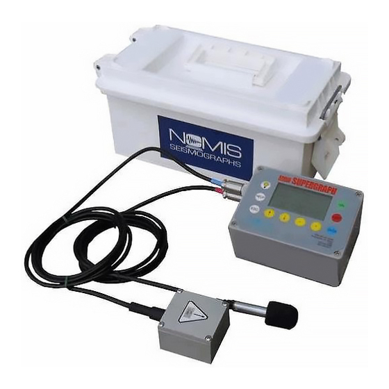
Instrument and all accessories fit neatly into the sturdy plastic, watertight carrying case. Gel cell rechargeable battery powers the unit. What Comes with the Mini-SuperGraph II? The following items are included in your Mini-SuperGraph II package: Mini-SuperGraph II unit User Guide Transducer Watertight carrying case ... -
Page 6: Operating Instructions
Operating Instructions Point the arrow on the transducer toward the vibration source. IMPORTANT: Connect the transducer and/or microphone cables before turning the instrument on. The transducer and microphone plugs are color coded to allow for easy connections. The quick lock ring on each connector is designed to prevent the connection from coming out. - Page 7 See the Transducer Placement Procedure on pages 10-13 for further instructions on how to make a stable placement. Press the green ON button and WAIT 60 SECONDS for the Nomis Main Menu to appear. Use the ↑ and ↓ keys to select the type of monitoring you want to use (See the Monitor Modes section for details about each available option): ...
- Page 8 This mode provides both the data collection from a period of time and detailed analysis of events over their trigger level. The Super Graphics program allows you to match these files together for a complete analysis. After you select a mode, the screen will display MONITOR and EDIT. ...
- Page 9 the saved data (use at least one character for this name). These saved settings will appear on the NOMIS MAIN MENU under option number 4: SAVED SETTINGS. You can save a maximum of 14 settings. Once monitoring is complete, press ESC and then ENTER to stop monitoring. To turn the instrument off, press the red OFF button.
-
Page 10: Other Operating Information
Other Operating Information Press ESC at any point to leave the current operation or reverse the previous operation. To stop monitoring, always press ESC first and then press ENTER. You can use the HELP menu to view or change many features for the Mini- SuperGraph II, such as change the date and time, erase memory, change the language, check event summaries &... - Page 11 o Red to green flashing light indicates monitoring while charging. o Quick flashing of green light during monitoring indicates the unit is writing data. Note that the LCD screen may be slow to update in certain configurations during this time and will return to normal updating speed once the data write is complete.
-
Page 12: Transducer Placement Procedure
Transducer Placement Procedure Placement of the transducer block is critical when taking vibration readings. This block must always make firm contact with the surface to ensure an accurate vibration reading. There are very few incidents where the transducer block can be simply placed on the surface for an accurate vibration measurement. - Page 13 Placement Instructions Method Bury This is the most accepted procedure and will produce the most dependable Transducer results. For more information about this procedure, refer to the U.S. Bureau of in Soil Mines Bulletin RI 8506 – Measurement of Blast Induced Ground Vibrations and Seismograph Calibration.
- Page 14 Placement Instructions Method transducer block. This will provide a solid coupling with the soil so that no slippage can occur. Bolt When soil is not available to bury the transducer, you can bolt the transducer Transducer block to a rock or concrete surface. Depending on the anchors available in Block your area, an anchor can be placed in the concrete or rock and a threaded bolt placed through the hole to bolt the transducer block into place.
- Page 15 Placement Instructions Method dig a hole to bury the transducer block. However, once vibration levels exceed .25 ips (6 mm/s), consider burying the transducer block. Sand Bag As a last resort it may be necessary to sandbag the transducer block to on Top of eliminate slippage.
- Page 16 We do not want operators to falsely assume that leveling is the most important aspect of proper transducer installation. The type of geophone elements used in NOMIS Seismographs only require a leveling of 20 degrees or less against the horizon, according to the geophone manufacturer.
-
Page 17: Monitor Modes
Monitor Modes Three monitoring modes are available with the Mini-SuperGraph II: SELF TRIGGER, BAR GRAPH, and COMBO. If you want to modify the settings for a monitoring mode, select that mode, press the ↓ button to select EDIT and press ENTER. With the EDIT option, a different screen will display each time you press ENTER. -
Page 18: Self Trigger (Waveform) Mode
All activity is stored in internal memory in a numbered event format. Once the recording is complete, the Mini-SuperGraph II returns to a wait mode for the next event that exceeds the trigger levels. - Page 19 Company – User setting for record Seis. Location – User setting for record Notes – User setting for record Distance to source – None, 1-99999 ft (User setting for record) Weight Per Delay – None, 1-99999 lbs (User setting for record) ...
- Page 20 Save Setup – Choose YES or NO to save the setup for later use. If you choose to save settings, enter a name to identify the saved settings. Additional Settings: Alarm 1: Able to set as follows: Off, Seismic, Air, both. If you choose Seismic, Air, or Both, set the trigger level for the sensor(s) selected.
- Page 21 High Level Steps for SELF TRIGGER Mode: Set to Monitor and record event(s) Allow it to go to sleep Wake it up Exit...
-
Page 22: Bar Graph
BAR GRAPH This mode is designed for situations where large data collection is needed for long periods of time (normally over 60 seconds and lasting for hours or days). Seismic and/or air data is collected and recorded in a bar graph (histogram) format and stored in the internal memory for future use. - Page 23 When you select BAR GRAPH from the main menu and choose EDIT, you will be able to modify the following settings: Sample Rate – 512, 1024, 2048, 4096, 8192. Faster sample rates are more accurate at higher frequencies, but will create larger files. ...
- Page 24 Bar Interval – 1, 10, 20, 30, 40, 50, 60 seconds. This is the amount of time each bar represents. Summary Interval – 5 min., 10 min., 30 min., 1 hour, 2 hours, 4 hours, 8 hours, 12 hours. Indicates how often a complete summary is saved in the record.
- Page 25 High Level Steps for BAR GRAPH Mode: 1. Set to monitor and record for 10 minutes 2. Allow it to go to sleep 3. Wake it up 4. Exit...
-
Page 26: Combo
COMBO COMBO mode, a combination of both SELF TRIGGER and BAR GRAPH modes, is designed for situations where both types of data are needed. The files for these will be split into each type and stored. This mode provides both the data collection from a period of time and detailed analysis of events over their trigger level. -
Page 27: Help Menu
Help Menu Press the HELP key on the unit for assistance with the normal features of the Mini- SuperGraph II. You can use the HELP menu at any time before monitoring starts. The HELP function has 2 different menus: 1: CONFIG &... -
Page 28: Configurations And Options
Configurations and Options Feature Description Alarm Output Use this option to turn the external alarm feature on or off. With this feature Mode you can connect external alarms to the unit to indicate when vibration and/or air limits have been exceeded. Choose DISABLED or ENABLED. If you enable the alarm here, you can then go to the Edit menu for the monitoring mode to select two (2) limits of your choice as a caution and not to exceed limit. - Page 29 Feature Description with that record. Bar graph does not store a calibration graph with the event. If a calibration graph is required, enable this option. This feature is intended for use on instruments that are left in place for a number of days at a time.
- Page 30 This option is intended for instances when an operator may forget to put the Mini-SuperGraph II into monitor mode. If you set this feature to “no auto monitor”, the operator will need to press all keys necessary to begin monitoring with the unit.
- Page 31 Feature Description Baud Rate Use this option to set the baud rate of the instrument when some type of modem is in use. The default value for this setting is 38400. Other options are 115200, 57600, 19200 and 9600. This is used for serial communication with the PC as well as modem communication.
- Page 32 Feature Description Erase Use this option if you want to clear all stored events from the memory. Memory Choose YES to erase the memory. CAUTION: With this feature all previously stored data will be permanently deleted. Make sure you have downloaded all useable data prior to executing the erase procedure.
- Page 33 Feature Description this, choose NO on the first erase memory screen and you will have the option to erase saved settings. Events Use this option to view all events stored in memory. The LCD displays the Summary event number, date, and time of the event. The far right side will display a letter to indicate the mode of operation used when the event was recorded: W for waveform, B for bar graph, C for combo mode, P for calibration pulse.
- Page 34 Feature Description memory is full, but it will write over the oldest events it has stored in memory. Flash Stats Use this option to see how much memory has been used and how much remains at any given time. It also indicates whether or not Flash Wrapping has been activated and how many waveforms or bar graph hours remain at current settings before an overwrite will occur.
- Page 35 Feature Description Press the + and – keys and the bar at the bottom will indicate the change. Select Save Changes to save the settings. You can press the – or + keys at any time to change the LCD contrast without having to use the HELP menu.
- Page 36 Monitor Log Use this option to view the dates and times that the seismograph was monitoring. For the Mini-SuperGraph II, the only valid option is VIEW MONITOR LOG. The log will show the start time, the number of events recorded, the event number of each recorded event, and the time the seismograph stopped monitoring.
- Page 37 Feature Description Sensor Use this option to view the type sensor provided with the unit and the Gain/Type maximum vibration level for that sensor. The sensors available are X1 (20 IPS/508 mm max), X2 (10 IPS/254 mm max), X4 (5 IPS/127 mm max), and X8 (2.5 IPS/63 mm max).
- Page 38 Feature Description 2. HOURLY – Once every hour. 3. DAILY (EVERY DAY) – The same time every day, seven days per week, 365 days per year. 4. DAILY (WEEKDAYS) – The same time, Monday – Friday, of each week, 52 weeks per year.
- Page 39 Feature Description 5. Press ESC to go back to the MAIN MENU and select the recording mode you want to use. 6. After selecting the recording mode (self-trigger, bar graph, combo, saved settings), use the EDIT option to view the operating parameters. After you have reviewed these, the LCD will display MONITOR or EDIT.
- Page 40 Feature Description time. In this case, select the next day for the beginning of Timer Mode Units of Air Use this option to choose between DECIBEL and MILLIBAR units. All data stored in the unit will be changed to the selection of choice. Units of Use this option to choose between INCHES and MILLIMETERS.
-
Page 41: Technical Specifications
Technical Specifications Seismic: Sound: Monitoring with Standard Triaxial Weighting Scales: Linear (flat) Geophone Linear Range: 92-148dB Range: 0 - 10in/s (0-254mm/s) - Linear Resolution: 0.00015625mb Standard @ 16-bit accuracy Maximum Resolution: 0.00003 Linear Accuracy: +/- 1dB or +/- in/s (0.00078mm/s) @ 16-bit 10% whichever is greater ... - Page 42 Waveform Recorded Data: Record Modes: Waveform, Combo & Manual Seismic Trigger Range: 0.02 - 10.24 in/s (0.508 - 260.096mm/s) X2 sensor low sensitivity Sound Trigger Range (Linear): 92 - 148dB, no trigger (other levels optional) Sample Rate: 1024 - 16384 Standard, higher rates optional ...
-
Page 43: Physical Specifications
Physical Specifications Dimensions: 6 x 4.25 x 3 in/ (152 x 108 x 76 mm) Weight: 4.1 lbs. (1.9 kgs) Battery: Up to 7 days duration per recharge (monitor mode) Display - LCD: 8 lines x 21 characters w/backlight ... - Page 44 For questions or information, please contact us: 3728 4th Avenue South Birmingham, AL 35222-2420 Phone: 205/592-2488 or 800/749-2477 Fax: 205/592-0213 Website: www.nomis.com E-mail: sales@nomis.com...
Need help?
Do you have a question about the Mini-SuperGraph II and is the answer not in the manual?
Questions and answers
What is the Price of the equipment